- Author Matthew Elmers elmers@military-review.com.
- Public 2023-12-16 21:49.
- Last modified 2025-01-24 09:17.
Until a certain time, Hitler's Germany did not pay much attention to the projects of gas turbine power plants for ground vehicles. So, in 1941, the first such unit was assembled for an experimental locomotive, but its tests were quickly curtailed due to economic inexpediency and the presence of more priority programs. Work in the direction of gas turbine engines (GTE) for ground vehicles continued only in 1944, when some of the negative features of the existing technology and industry were especially pronounced.
In 1944, the Army's Armaments Directorate launched a research project on GTE for tanks. There were two main reasons for the new engines. Firstly, the German tank building at that time set a course for heavier combat vehicles, which required the creation of an engine of high power and small dimensions. Secondly, all available armored vehicles used to some extent scarce gasoline, and this imposed certain restrictions related to operation, economics and logistics. Promising gas turbine engines, as German industry leaders then considered, could consume less high-quality and, accordingly, cheaper fuel. Thus, at that time, from the point of view of economics and technology, the only alternative to gasoline engines was a gas turbine engine.
At the first stage, the development of a promising tank engine was entrusted to a group of designers from Porsche, headed by engineer O. Zadnik. Several related enterprises were supposed to assist the Porsche engineers. In particular, the SS Engine Research Department, led by Dr. Alfred Müller, was involved in the project. Since the mid-thirties, this scientist has been working on the subject of gas turbine installations and participated in the development of several aircraft jet engines. By the time the creation of a gas turbine engine for tanks began, Müller had completed the turbocharger project, which was later used on several types of piston engines. It is noteworthy that in 1943, Dr. Müller repeatedly made proposals regarding the start of the development of tank gas turbine engines, but the German leadership ignored them.
Five options and two projects
By the time the main work began (mid-summer 1944), the leading role in the project had passed to the organization headed by Müller. At this time, the requirements for a promising gas turbine engine were determined. It was supposed to have a power of about 1000 hp. and an air consumption of the order of 8.5 kilograms per second. The temperature in the combustion chamber was set by the terms of reference at 800 °. Due to some of the characteristic features of gas turbine power plants for ground vehicles, before starting the development of the main project, several auxiliary ones had to be created. A team of engineers led by Müller simultaneously created and considered five options for the architecture and layout of the gas turbine engine.
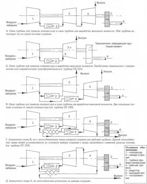
The schematic diagrams of the engine differed from each other in the number of stages of the compressor, turbine and the location of the power turbine associated with the transmission. In addition, several options for the location of the combustion chambers were considered. So, in the third and fourth versions of the GTE layout, it was proposed to divide the air flow from the compressor into two. One stream in this case had to go into the combustion chamber and from there to the turbine rotating the compressor. The second part of the incoming air, in turn, was injected into the second combustion chamber, which delivered hot gases directly to the power turbine. Also, options were considered with a different position of the heat exchanger for preheating the air entering the engine.
In the first version of the promising engine, which reached the stage of full-fledged design, a diagonal and axial compressor, as well as a two-stage turbine, should have been located on the same axis. The second turbine was supposed to be placed coaxially behind the first and connected to the transmission units. At the same time, the power turbine supplying power to the transmission was proposed to be mounted on its own axis, not connected to the axis of the compressors and turbines. This solution could simplify the design of the engine, if not for one serious flaw. So, when removing the load (for example, during a gear change), the second turbine could spin up to such speeds at which there was a risk of destruction of the blades or hub. It was proposed to solve the problem in two ways: either to slow down the working turbine at the right moments, or to remove gases from it. Based on the analysis results, the first option was chosen.
And yet, the modified first version of the tank GTE was too complicated and expensive for mass production. Müller continued further research. To simplify the design, some original parts were replaced with corresponding units borrowed from the Heinkel-Hirt 109-011 turbojet engine. In addition, several bearings were removed from the design of the tank engine, on which the engine axles were held. Reducing the number of shaft supports to two simplified assembly, but eliminated the need for a separate axle with a turbine that transmits torque to the transmission. The power turbine was installed on the same shaft on which the compressor impellers and the two-stage turbine were already located. The combustion chamber is equipped with original rotating nozzles for spraying fuel. In theory, they made it possible to inject fuel more efficiently, and also helped to avoid overheating of certain parts of the structure. An updated version of the project was ready in mid-September 1944.
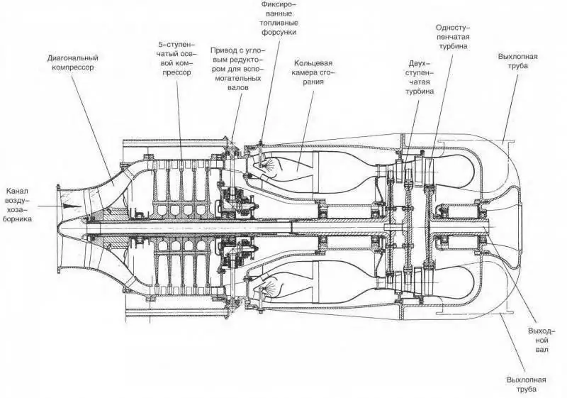
The first gas-tube unit for armored vehicles
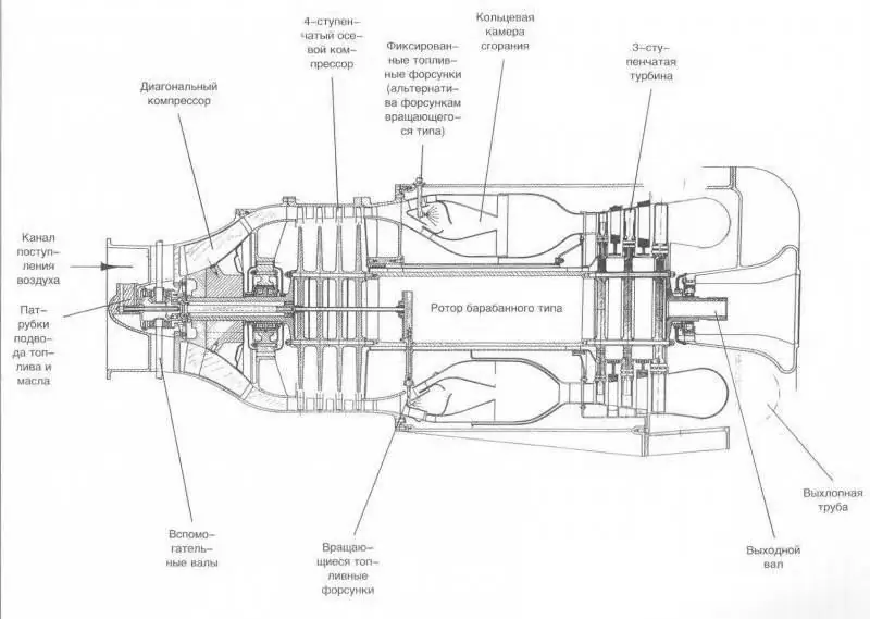
The first gas-tube unit for armored vehicles
This option was also not without its drawbacks. First of all, the claims caused difficulties with maintaining the torque on the output shaft, which was actually an extension of the engine's main shaft. The ideal solution to the problem of power transmission could be the use of an electric transmission, but the shortage of copper made such a system to be forgotten. As an alternative to electric transmission, a hydrostatic or hydrodynamic transformer was considered. When using such mechanisms, the efficiency of power transmission was slightly reduced, but they were significantly cheaper than a system with a generator and electric motors.
GT 101 engine
Further development of the second version of the project led to further changes. So, in order to preserve the performance of the GTE under shock loads (for example, when a mine explodes), a third shaft bearing was added. In addition, the need to unify the compressor with aircraft engines led to a change in some parameters of the tank GTE operation. In particular, the air consumption has increased by about a quarter. After all the modifications, the tank engine project received a new name - GT 101. At this stage, the development of a gas turbine power plant for tanks reached the stage when it was possible to begin preparations for the construction of the first prototype, and then the tank equipped with a gas turbine engine.
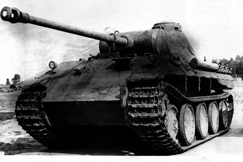
Nevertheless, the fine-tuning of the engine dragged on and by the end of the autumn of 1944, work on installing a new power plant on the tank had not begun. At that time, German engineers were only working on placing the engine on existing tanks. It was originally planned that the base for the experimental GTE would be the heavy tank PzKpfw VI - "Tiger". However, the engine compartment of this armored vehicle was not large enough to accommodate all the necessary units. Even with a relatively small displacement, the GT 101's engine was too long for a Tiger. For this reason, it was decided to use the PzKpfw V tank, also known as the Panther, as the base test vehicle.
At the stage of finalizing the GT 101 engine for use on the Panther tank, the customer, represented by the Land Forces Armaments Directorate, and the project executor, determined the requirements for the prototype. It was assumed that the gas turbine engine would bring the specific power of a tank with a combat weight of about 46 tons to the level of 25-27 hp. per ton, which will significantly improve its running characteristics. At the same time, the requirements for maximum speed have hardly changed. Vibration and shock from high-speed driving significantly increased the risk of damage to chassis components. As a result, the maximum permissible speed was limited to 54-55 kilometers per hour.
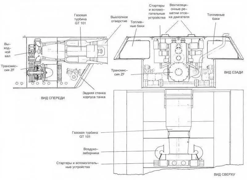
Gas turbine unit GT 101 in the tank "Panther"
As in the case of the Tiger, the Panther's engine compartment was not large enough to accommodate the new engine. Nevertheless, the designers under the leadership of Dr. Miller managed to fit the GT 101 GTE into the available volumes. True, the large engine exhaust pipe had to be placed in a round hole in the rear armor plate. Despite the seeming strangeness, such a solution was considered convenient and suitable even for mass production. The GT 101 engine itself on the experimental "Panther" was supposed to be placed along the axis of the hull, with a shift upward, to the roof of the engine compartment. Next to the engine, in the fenders of the hull, several fuel tanks were placed in the project. The place for the transmission was found directly under the engine. The air intake devices were brought to the roof of the building.
The simplification of the design of the GT 101 engine, due to which it lost its separate turbine associated with the transmission, entailed difficulties of a different nature. For use with the new GTE, a new hydraulic transmission had to be ordered. Organization ZF (Zahnradfabrik of Friedrichshafen) in a short time created a three-stage torque converter with a 12-speed (!) Gearbox. Half of the gears were for road driving, the rest for off-road driving. In the engine-transmission installation of the experimental tank, it was also necessary to introduce automation that monitored the engine operating modes. A special control device was supposed to monitor the engine speed and, if necessary, increase or decrease the gear, preventing the GTE from entering unacceptable operating modes.
According to the calculations of scientists, the GT 101 gas turbine with a transmission from ZF could have the following characteristics. The maximum turbine power reached 3750 hp, 2600 of which were taken by the compressor to ensure the engine operation. Thus, “only” 1100-1150 horsepower remained on the output shaft. The rotational speed of the compressor and turbines, depending on the load, fluctuated between 14-14.5 thousand revolutions per minute. The temperature of the gases in front of the turbine was kept at a predetermined level of 800 °. The air consumption was 10 kilograms per second, and the specific fuel consumption, depending on the operating mode, was 430-500 g / hp h.
GT 102 engine
With a uniquely high power, the GT 101 tank gas turbine engine had an equally remarkable fuel consumption, approximately twice as high as those of the gasoline engines available at that time in Germany. In addition to fuel consumption, the GTE GT 101 had several more technical problems that required additional research and correction. In this regard, a new project GT 102 began, in which it was planned to maintain all the successes achieved and get rid of the existing shortcomings.
In December 1944, A. Müller came to the conclusion that it was necessary to return to one of the earlier ideas. To optimize the operation of the new GTE, it was proposed to use a separate turbine on its own axle, connected to the transmission mechanisms. At the same time, the power turbine of the GT 102 engine had to be a separate unit, not placed coaxially with the main units, as previously proposed. The main block of the new gas turbine power plant was GT 101 with minimal changes. It had two compressors with nine stages and a three-stage turbine. When developing the GT 102, it turned out that the main block of the previous GT 101 engine, if necessary, can be placed not along, but across the engine compartment of the Panther tank. And so they did when assembling the units of the experimental tank. The air intake devices of the gas turbine engine were now located on the roof at the left side, the exhaust pipe at the right side.
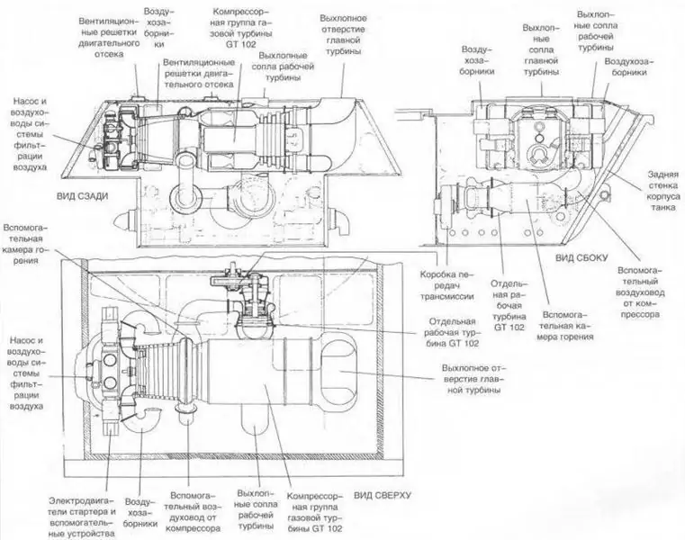
Gas turbine unit GT 102 in the tank "Panther"
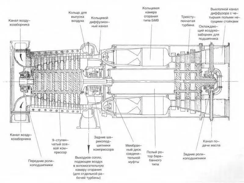
Gas turbine compressor unit GT 102
Between the compressor and the combustion chamber of the main engine block, a pipe was provided for bleeding air to the additional combustion chamber and turbine. According to calculations, 70% of the air entering the compressor had to go through the main part of the engine and only 30% through the additional, with a power turbine. The location of the additional block is interesting: the axis of its combustion chamber and power turbine should have been located perpendicular to the axis of the main engine block. It was proposed that the power turbine units be placed below the main unit and equipped with their own exhaust pipe, which was removed in the middle of the roof of the engine compartment.
The "congenital disease" of the GT 102's gas turbine engine design was the risk of over-spinning the power turbine with subsequent damage or destruction. It was proposed to solve this problem in the simplest way: to place valves to control the flow in the pipe supplying air to the additional combustion chamber. At the same time, calculations showed that the new GT 102 GTE may have insufficient throttle response due to the peculiarities of the operation of a relatively light power turbine. The design specifications, such as output shaft power or turbine power of the main unit, remained at the level of the previous GT 101 engine, which can be explained by the almost complete absence of major design changes, except for the appearance of the power turbine unit. Further improvement of the engine required the use of new solutions or even the opening of a new project.
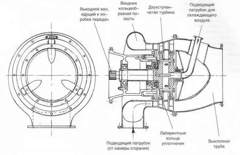
Separate working turbine for GT 102
Before starting the development of the next GTE model, called the GT 103, Dr. A. Müller made an attempt to improve the layout of the existing GT 102. The main problem of its design was the rather large dimensions of the main unit, which made it difficult to place the entire engine in the engine compartments of the tanks available at that time. To reduce the length of the engine-transmission unit, it was proposed to design the compressor as a separate unit. Thus, three relatively small units could be placed inside the engine compartment of the tank: a compressor, a main combustion chamber and a turbine, as well as a power turbine unit with its own combustion chamber. This version of the GTE was named GT 102 Ausf. 2. In addition to placing the compressor in a separate unit, attempts were made to do the same with the combustion chamber or turbine, but they did not have much success. The design of the gas turbine engine did not allow itself to be divided into a large number of units without noticeable losses in performance.
GT 103 engine
An alternative to the GT 102 Ausf gas turbine engine. 2 with the possibility of "free" arrangement of units in the existing volume was the new development of GT 103. This time the German engine builders decided to focus not on the convenience of placement, but on the efficiency of work. A heat exchanger was introduced into the engine equipment. It was assumed that with its help the exhaust gases will heat the air entering through the compressor, which will achieve tangible fuel savings. The essence of this solution was that the preheated air would make it possible to spend less fuel to maintain the required temperature in front of the turbine. According to preliminary calculations, the use of a heat exchanger could reduce fuel consumption by 25-30 percent. Under certain conditions, such savings were able to make the new GTE suitable for practical use.
The development of the heat exchanger was entrusted to "subcontractors" from the company Brown Boveri. The chief designer of this unit was V. Khrinizhak, who had previously taken part in the creation of compressors for tank gas turbine engines. Subsequently, Chrynižak became a renowned specialist in heat exchangers and his participation in the GT 103 project was probably one of the prerequisites for this. The scientist applied a rather bold and original solution: the main element of the new heat exchanger was a rotating drum made of porous ceramics. Several special partitions were placed inside the drum, which ensured the circulation of gases. During operation, hot exhaust gases passed inside the drum through its porous walls and heated them. This happened during half a drum turn. The next half-turn was used to transfer heat to the air passing from the inside to the outside. Thanks to the system of baffles inside and outside the cylinder, air and exhaust gases did not mix with each other, which excluded engine malfunctions.
The use of the heat exchanger caused serious controversy among the authors of the project. Some scientists and designers believed that the use of this unit in the future would make it possible to achieve high power and relatively low air flow rates. Others, in turn, saw in the heat exchanger only a dubious means, the benefits of which could not significantly exceed the losses from the complication of the design. In the dispute about the need for a heat exchanger, the supporters of the new unit won. At some point, there was even a proposal to equip the GT 103 gas turbine engine with two devices for preheating the air at once. The first heat exchanger, in this case, had to heat the air for the main engine block, the second for the additional combustion chamber. Thus, the GT 103 was actually a GT 102 with heat exchangers introduced into the design.
The GT 103 engine was not built, which is why it is necessary to be content with its calculated characteristics only. Moreover, the available data on this GTE were calculated even before the end of the creation of the heat exchanger. Therefore, a number of indicators in practice, probably, could turn out to be significantly lower than expected. The power of the main unit, generated by the turbine and absorbed by the compressor, was supposed to be equal to 1400 horsepower. The maximum design speed of rotation of the compressor and turbine of the main unit is about 19 thousand revolutions per minute. Air consumption in the main combustion chamber - 6 kg / s. It was assumed that the heat exchanger will warm up the incoming air to 500 °, and the gases in front of the turbine will have a temperature of about 800 °.
The power turbine, according to calculations, was supposed to rotate at a speed of up to 25 thousand rpm and give 800 hp on the shaft. The air consumption of the additional unit was 2 kg / s. The temperature parameters of the incoming air and exhaust gases were supposed to be equal to the corresponding characteristics of the main unit. The total fuel consumption of the entire engine with the use of appropriate heat exchangers would not exceed 200-230 g / hp h.
Results of the program
The development of German tank gas turbine engines began only in the summer of 1944, when Germany's chances of winning the Second World War were dwindling every day. The Red Army attacked the Third Reich from the east, and the troops of the United States and Great Britain came from the west. In such conditions, Germany did not have sufficient opportunities for full-fledged management of the mass of promising projects. All attempts to create a fundamentally new engine for tanks rested on a lack of money and time. Because of this, by February 1945, there were already three full-fledged projects of tank gas turbine engines, but none of them even reached the stage of prototype assembly. All work was limited only to theoretical studies and tests of individual experimental units.
In February 1945, an event took place that can be considered the beginning of the end of the German program for the creation of tank gas turbine engines. Dr. Alfred Müller was removed from his post as head of the project, and his namesake, Max Adolf Müller, was appointed to the vacant position. M. A. Müller was also a prominent specialist in the field of gas turbine power plants, but his arrival on the project stalled the most advanced developments. The main task under the new head was the fine-tuning of the GT 101 engine and the beginning of its serial production. Less than three months remained until the end of the war in Europe, which is why the change in project leadership did not have time to lead to the desired result. All German tank GTEs remained on paper.
According to some sources, the documentation for the projects of the "GT" line fell into the hands of the allies and they used it in their projects. However, the first practical results in the field of gas turbine engines for ground vehicles, which appeared after the end of World War II outside Germany, had little in common with the developments of both Dr. Müller. As for gas turbine engines designed specifically for tanks, the first serial tanks with such a power plant left the assembly shops of factories only a quarter of a century after the completion of German projects.


