- Author Matthew Elmers [email protected].
- Public 2023-12-16 21:49.
- Last modified 2025-01-24 09:17.
Tank "Object 432" was developed in May 1961 in the design bureau (department 60) of the plant. Malyshev (Kharkov) under the leadership of the chief designer A. A. Morozov on the basis of the decree of the Central Committee of the CPSU and the Council of Ministers of the USSR No. 141-58 of February 17, 1961. The technical design and the manufacture of prototypes of the machine were refined in accordance with the decree of the Council of Ministers of the USSR No. 957-407 of October 24, 1961. The chassis model of the tank without a turret with weapons assembled in March 1962 After installing the turret with weapons in June 1962, it passed factory tests, which ended on August 15, 1962. The first full-fledged model of the Object 432 tank was manufactured in September-October 1962. In total, until the end of December 1962. plant them. V. A. Malysheva produced three prototypes. One of them (the second) is a restored running mock-up of a tank with weapons, released in March 1962. In the period from November 11, 1962 to March 30, 1963, all three prototypes (as they were manufactured) passed the second stage of tests (running and field tests).
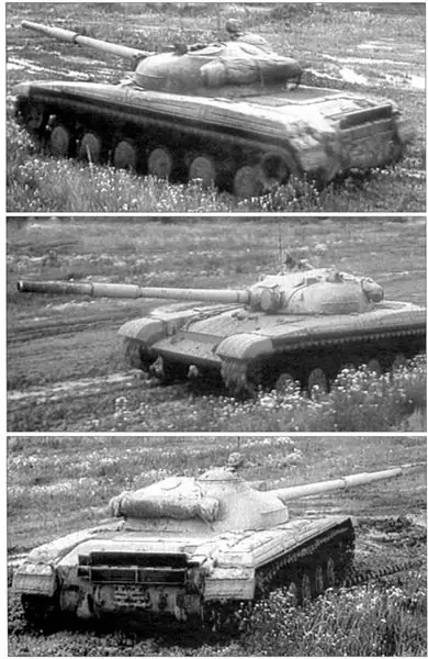
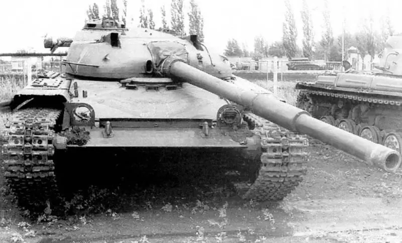
One of the first prototypes of the Object 432 tank
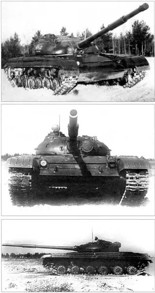
Serial sample of the tank "Object 432"
Combat weight - 35 tons; crew - 3 people; weapons: cannon - 115 mm, smoothbore, 1 machine gun - 7, 62 mm; armor protection - anti-cannon; engine power - 538 kW (700 hp); the maximum speed is 65 km / h.
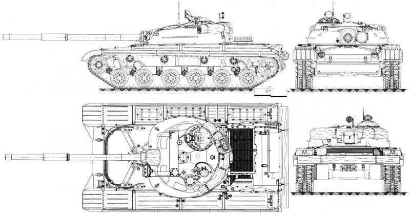
General view of the tank "Object 432" produced before July 1964
In accordance with the decree of the Central Committee of the CPSU and the Council of Ministers of the USSR No. 395-141 of March 28, 1963, the plant named after V. A. Malysheva began assembling a pilot batch for military trials, as well as preparing for production of the Object 432 tank according to the technical drawings of the chief designer. Simultaneously with the release of the pilot batch in the period from November 1963 to July 1964, two previously manufactured factory samples passed the third stage of forced tests. The first ten vehicles of the pilot batch were ready by the beginning of March 1964, of which three tanks in the period from May to June 1964 underwent control tests, which showed unsatisfactory results. Nevertheless, continuing the production of the car, by January 1, 1966, the plant named after. V. A. Malysheva produced 254 Object 432 tanks (of which three were intended for the installation of a B-45 diesel engine and were later named Object 436).
Tank "Object 432" had a classic layout with a transverse engine and a crew of three. A feature of the layout was its high density, as well as the minimum overall dimensions of the tank, especially in height (2, 17 m), which provided it with the smallest booked volume of all domestic medium tanks. This was achieved by excluding the loader from the crew and using a loading mechanism, a specially designed low-height engine and the presence of a stamping in the bottom of the hull to accommodate the driver's seat.
The control compartment was located in the bow of the hull. In the center of the control compartment (along the longitudinal axis of the machine) there was a driver's seat, in front of which steering levers, a fuel supply pedal and a transmission pedal (BKP shutdown pedal) were installed on the bottom of the hull. On the upper inclined sheet of the bow of the hull, in front of the driver's seat, there was a gyro-compass GPK-59, a relay distribution box KRR-2 and an AS-2 automatic machine of the UA PPO system, a stopping brake pedal, a crane with a valve for hydropneumatic cleaning of observation devices, a valve for starting the engine with compressed air, a fan for blowing the driver, two signal lamps for the cannon's exit beyond the dimensions of the body and a light for lighting the gear selector.
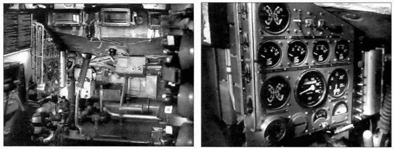
Department of management of the tank "Object 432". Instrument panel of the mechanic-driver of the tank "Object 432".
To the right of the driver's seat on the bottom were installed a gear selector (gear lever), a moisture collector, an air bleed valve, as well as a right fuel tank and a rack tank with part of the gun ammunition. In front of the selector, under the right fuel tank, there were two compressed air cylinders. In addition, a KUV-5 supercharger control box, a DP-3B roentgen meter, an RTS-27-4 temperature controller for electrical heating of observation devices, a KD-1 dynamic braking box and a KRPU PAZ system junction box were attached to the right fuel tank.
To the left of the driver's seat, on the bottom of the hull, there were handles for manual fuel feed drives and shutters of the cooling system, a bow centrifugal water pump with an electromotive drive and a switch valve, a fuel filter, a fuel distribution valve, a manual fuel pump RNM-1 and a fuel supply valve to the heater. In addition, on the left were the left fuel tank, dashboard and batteries, above which the ballast and battery switch were attached. Three cylinders of the UA PPO system were located behind the batteries.
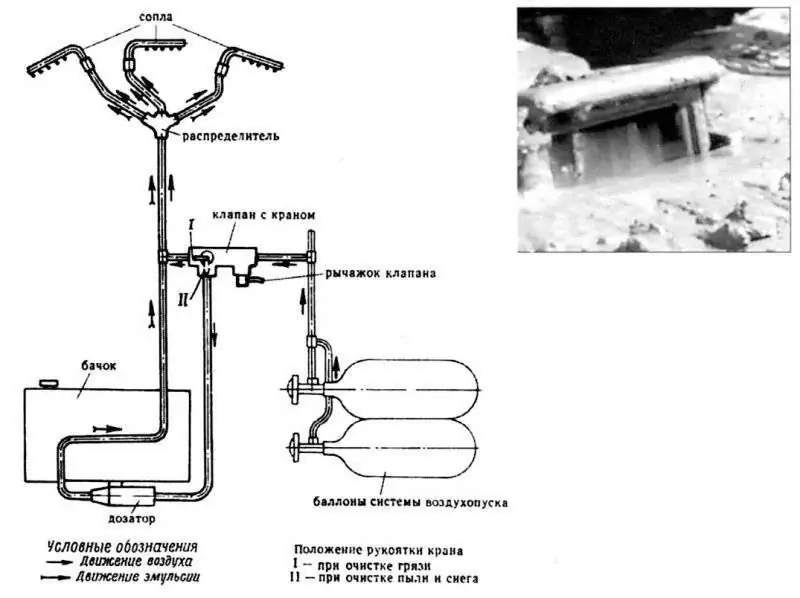
Diagram of the system of hydropneumatic cleaning of observation devices of the driver of the tank "Object 432" (left) and its work (right)
To observe the battlefield and drive the car in front of the driver in the upper frontal and zygomatic armor plates of the hull, three periscopic viewing devices TNPO-160 were mounted, providing a general sector of the horizontal view of 192 °. The observation devices had electric heating of the entrance and exit windows. When driving a tank at night, instead of a central viewing device, a TVN-2BM binocular night vision device was installed in the mine. Cleaning of the driver's viewing devices from dust, dirt and snow was carried out using a hydropneumatic cleaning system. A tank with a liquid and a dispenser for hydropneumatic cleaning of viewing devices, as well as a TVN-2BM device in a case, were located in the bow of the hull in the control compartment.
There was an entrance hatch in the roof of the control compartment above the driver's workplace. The swivel armored hatch cover was opened (raised) and closed using a closing mechanism (opening and closing the hatch both from the inside and outside was possible only at certain positions of the tower). To exclude the rotation of the tower from the electric drive when the driver's hatch was open, there was a lock associated with the position of the hatch cover. If necessary (with the stabilizer working), the driver could turn the turret to a position that allowed him to open the entrance hatch by turning on a special toggle switch.
To the left of the driver's entrance hatch there was a ventilation hatch, on the back on the turret plate there was a plafond of emergency lighting and the driver's TPUA-4 apparatus.
The design of the driver's seat provided its fixation in two positions: lower (when driving a tank in a combat manner) and upper (when driving a tank in a marching manner), as well as adjustment in height and along the body of the car to install the seat convenient for the driver position. When driving a tank in a marching manner, depending on weather conditions, a protective cover with a visor could be installed on the driver's hatch.
Behind the driver's seat in the bottom of the hull there was an emergency exit hatch, the cover of which opened outward (lowered to the ground).
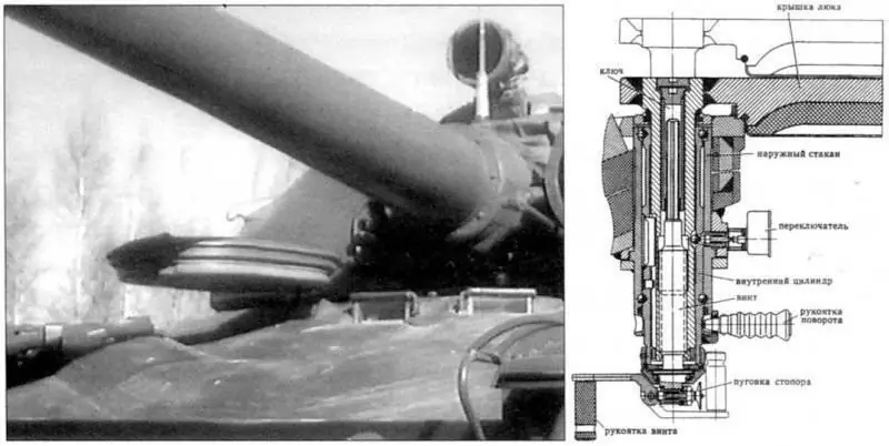
Entrance hatch and hatch closing mechanism for the driver of the tank "Object 432" (the hatch cover is open)
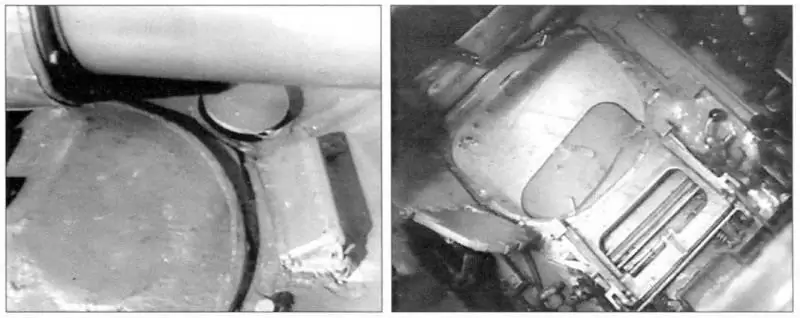
Placement of the ventilation hatch at the driver of the Object 432 tank. Emergency exit hatch of the Object 432 tank. The manhole cover is open (lowered to the ground).
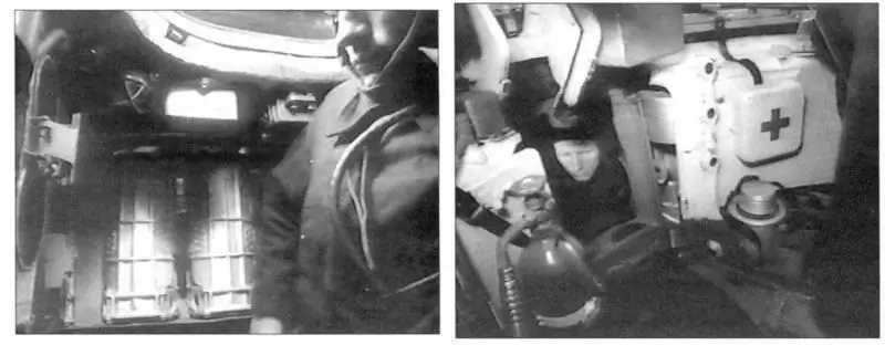
Isolation of the driver from the rest of the crew by the gun loading mechanism
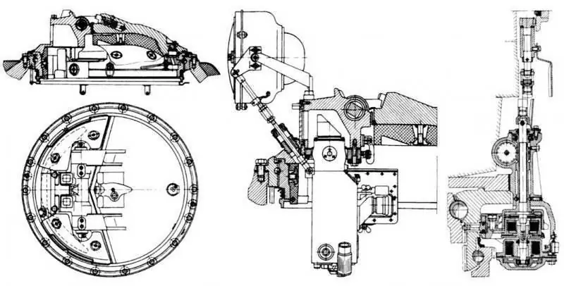
The commander's cupola, the installation of the TKN-3 device in the commander's cupola and the mechanism for holding the commander cupola of the tank "Object 432"
It should be noted that due to the adopted design of the loading mechanism, the driver was isolated from the other crew members by the cabin and the rotating conveyor. The transition of the driver from the control compartment to the fighting compartment was only possible when the turret with the gun was rearward and the two trays with shots from the loading mechanism conveyor were dismantled.
The fighting compartment was located in the middle of the hull in a special cabin and turret of the tank. The cockpit was an aluminum frame, which was attached to the upper shoulder strap of the tower support through intermediate brackets and rotated with it relative to the tank hull. It provided protection for the tank commander and gunner (their jobs were located, respectively, to the right and left of the gun) from the rotating conveyor of the loading mechanism. To move the crew members from the control compartment to the combat compartment and back, a hatch in the aft part of the cabin (along the longitudinal axis) served. The cockpit openings between the pillars, as well as its upper shelves, were closed with a lining.
The tower housed: the main and auxiliary weapons of the tank, components and assemblies of the stabilizer, a mechanism for loading a tank gun with a control panel, aiming and aiming devices, means of external and internal communication, as well as part of the devices of the PAZ, PPO systems, electrical equipment and ammunition.
Above the seat of the tank commander, on the roof of the tower, a commander's cupola was installed with an entrance hatch covered by an armored cover. The commander's cupola housed two TNP-160 observation devices, a combined (day and night) TKN-3 commander's observation device and an OU-3GK illuminator (on the turret roof).
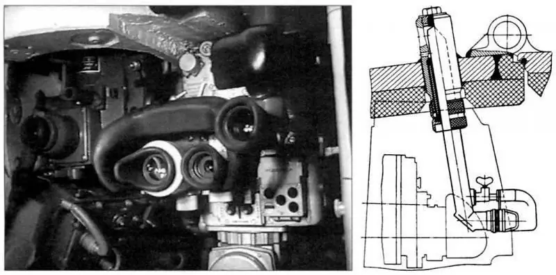
Gunner's workplace and installation of the VNM viewing device at the gunner of the "Object 432" tank
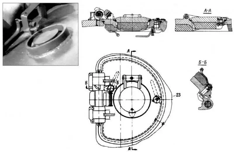
The hatch of the air intake of the tower of the tank "Object 432". Entrance hatch of the gunner of the tank "Object 432"
To facilitate the retention of the crosshair of the TKN-3 device on the selected target when targeting the gunner, the commander's cupola retention mechanism was used. It was located in the same housing with the tower stopper and included a drive gear connected to the teeth of the lower shoulder strap of the ball bearing of the tower, an electromagnetic clutch with a delivery link (friction clutch) and a drive that connected the mechanism to the gear ring of the inner shoulder strap of the commander's turret. In addition, a cosine potentiometer was mounted on the holding mechanism, intended to make corrections to the rangefinder sight when the tank moved to the target at an angle. The rotation of the commander's cupola when the button on the left handle of the TKN-3 device was pressed (on the right handle of the TKN-3 device there was a button to turn on the OU-3GK searchlight) was carried out at the speed of the turret throw (18 deg / s), but in the opposite direction.
The gunner for observation of the battlefield during the day had a monocular, stereoscopic, with independent stabilization of the field of view in the vertical plane, a tank sight-rangefinder TPD-43 or a periscopic observation device VNM, at night - a monocular periscope sight TPN-1 (TPN1-432) with a BT power supply -6-26M and infrared searchlight L-2AG (mounted on the bracket on the left on the front of the tower). To clean the protective glasses of the rangefinder sight and its base pipe from dirt, dust and snow, a hydropneumatic cleaning system was used, similar in design to the hydropneumatic cleaning system of the driver's viewing devices. However, this system used a separate two-liter air cylinder (mounted to the left of the gunner's seat, on the cockpit wall) and a reducer that lowered the air pressure to 1.37 MPa (14 kgf / cm2). In addition, to eliminate fogging and freezing of the protective glasses of the rangefinder sight and its base pipe, there was also a system for blowing them with air. It consisted of a centrifugal supercharger, which took air from the fighting compartment and supplied it through special air ducts through the outlet nozzles to the protective glasses of the sight head, the left head of the base pipe and the left window of the tower, as well as the right head of the base pipe and the right window of the tower.
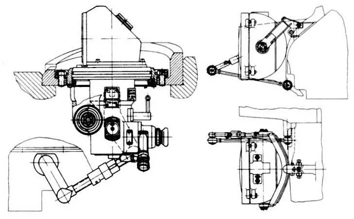
Installation of the TPN-1-432 night sight and the L-2AG infrared searchlight on the tower of the Object 432 tank
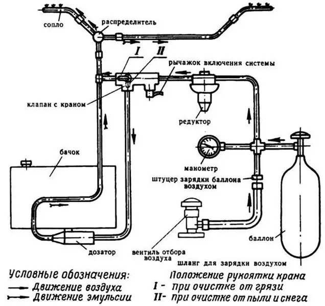
Diagram of the system of hydropneumatic cleaning of protective glasses of the rangefinder sight
For the gunner's landing and exit, there was a hatch above his workplace in the turret roof, which was closed by an armored cover. In the middle part of the hatch cover, a hatch was made for installing the OPVT air supply pipe, which was closed by a hinged cover on two hinges and locked with a lock that could only be opened with a special key. To facilitate opening the hatch covers of the tank commander and gunner, beam torsion bars made of steel plates were installed in their hinges.
In the fighting compartment, in the hull behind the cab and the conveyor at the MTO partition, there were two rear internal fuel tanks. A heater for the engine heating system with a heater was installed between the right rear fuel tank and the side. Above it, at the engine partition, a supercharger with a PAZ system filter was attached, and an exhaust fan was installed in a special window of the left rear fuel tank. On the left side, behind the batteries, a horizontal stabilizer hydraulic drive was mounted.
Removal of powder gases from the tank during firing, as well as blowing fresh air into the crew during the hot season, were provided by the ventilation system of the manned compartments. This system included a manually operated blower for opening and closing the valves, an easily removable electric fan (in front of the driver), turret air intake (on the aft sheet of the turret roof), hull air vents (on the zygomatic sheet of the roof to the left of the driver), and an exhaust fan. The exhaust fan was turned on by pressing the "Start" button on the KUV-5 box located in the commander's fighting compartment.
The MTO was located in the aft part of the tank and was separated from the fighting compartment by a sealed partition. In the compartment across the body, an engine was installed with power output to the drive wheels from both ends of the crankshafts through the right and left BKP, mounted in a block with coaxial planetary final drives. Between the engine and the engine bulkhead, the tanks of the engine (left) and transmission (right) lubrication systems were located.
Above the engine, at the left side of the hull, there was an air cleaner, and on the bottom under the air cleaner there was a feed pump for pumping out water when the tank crossed a water barrier along the bottom. On the starboard side, an expansion tank of the engine cooling system and a gas duct pipe were attached, which was connected with an annular expansion joint to the casing of the engine gas turbine. A stern fuel tank was installed between the engine and the aft hull sheet. The MTO also housed control drive units, an engine stopping mechanism (MOD), thermal smoke equipment (TDA), temperature sensors of the UA PPO system, control instrument sensors and a high-voltage torch heating coil. Due to the dense layout, the volume of the MTO was only 2.62 m3.
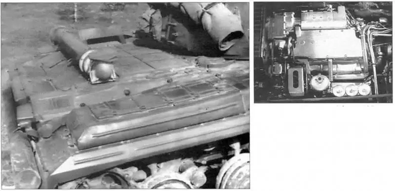
MTO tank "Object 432". View of the MTO tank "Object 432" with the roof raised.
The main weapon of the tank was a 115-mm smooth-bore stabilized in two planes tank gun D-68, separate-case loading with a wedge semiautomatic shutter of horizontal movement and an ejection mechanism for cleaning the bore from powder gases after firing. The bolt of the gun was equipped with a mechanism for re-cocking the striker and mechanisms that prevented mechanical self-release when a tank was moving with a loaded gun and from a shot when the bolt was not fully closed. A coaxial 7.62 mm PKT machine gun was installed on the right side of the gun cradle in a special bracket.
The TPD-43 rangefinder sight and the TPN-1 night sight were used to aim the cannon and the machine gun paired with it at the target when firing direct fire, and when firing from a cannon from closed firing positions - a side level and an azimuth indicator. The error in measuring the range using a rangefinder sight in the range of 1000-4000 m was 3-5%. Guidance of the twin weapon installation at the target was carried out using the 2E18 "Lilac" electro-hydraulic stabilizer from the handles of the control panel of the rangefinder sight or the handles of the hydraulic lifting mechanism of the gun and the manual turret rotation mechanism. The vertical guidance angles with the stabilizer turned off were in the range from -6 to + 14 °.
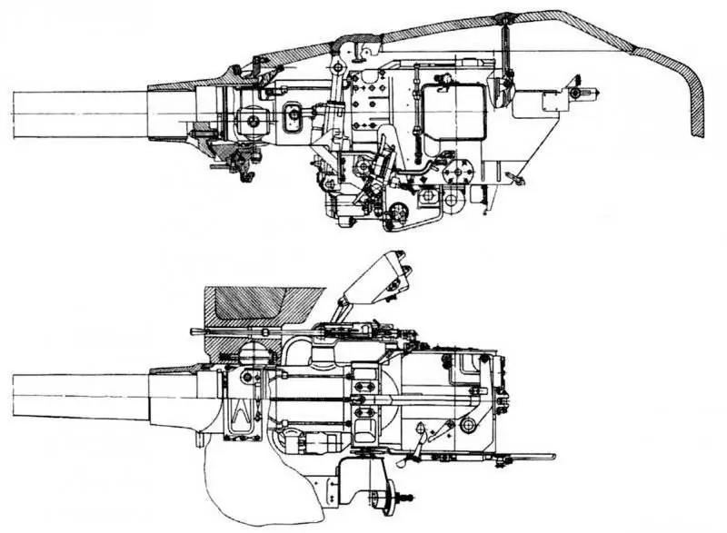
Installation of the D-68 cannon in the turret of the Object 432 tank
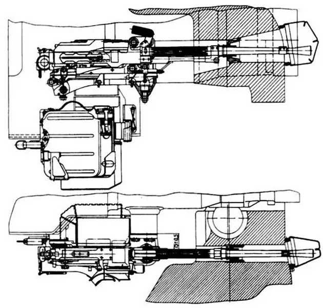
Installation of a coaxial PKT machine gun in the turret of the Object 432 tank
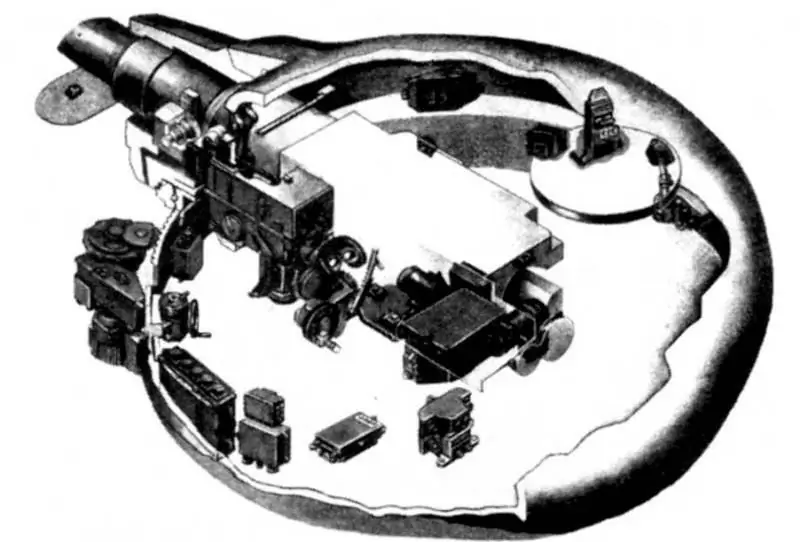
Placement of units and devices of the stabilizer 2E18 "Lilac" in the tank "Object 432"
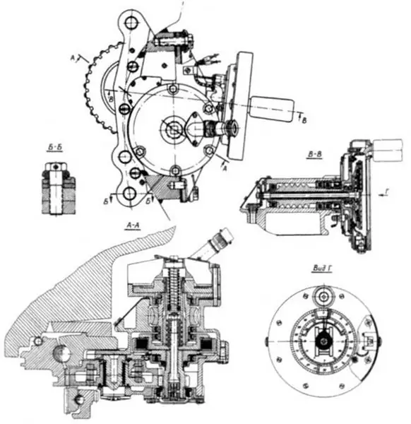
Mechanism of rotation of the turret with a manual drive of the tank "Object 432"
The aiming speeds of the paired installation from the control panel of the rangefinder sight (when the electric drive was operating) using hydraulic mechanisms were: vertically - from 0.05 to 3.5 deg / s, horizontally - from 0.05 to 18 deg / s … The turret was rotated in both stabilized and semi-automatic (unstabilized) guidance modes. When the electric drive was inoperative, the turret could be rotated using a manual swing mechanism located to the left of the gunner. Disconnection of the turret rotation mechanism with a manual drive during the operation of the hydraulic rotation mechanism and its activation was carried out by an electromagnetic clutch powered from the tank's on-board network. An azimuth indicator was located in the flywheel of the turret rotation mechanism with a manual drive, and its drive was located in the upper crankcase of the mechanism.
A cannon shot could be fired both with the help of electric (galvanosurgeon) and mechanical (manual) triggers. The electric release was carried out by pressing the button located on the right handle of the scope-rangefinder console, or by pressing the button located on the handle of the flywheel of the gun lifting mechanism. The mechanical (manual) release lever went out beyond the left shield of the gun guard. For firing a machine gun, a button on the left handle of the control panel of the rangefinder sight or a button on the flywheel handle of the turret rotation mechanism was used.
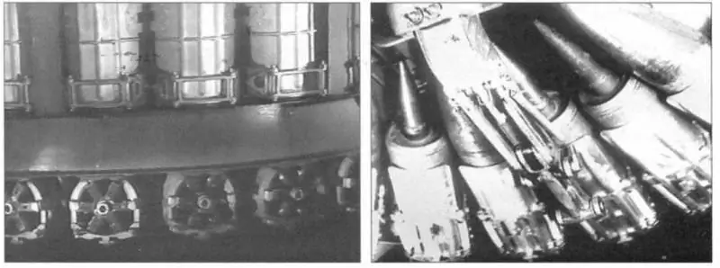
Conveyor of the mechanism for loading the cannon of the tank "Object 432". Right - Location of subcaliber and high-explosive fragmentation shells.
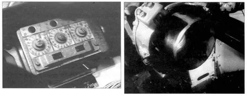
Control panel for the loading mechanism of the tank "Object 432". On the right - the catcher of the cannon loading mechanism of the "Object 432" tank with a metal tray of a partially combustible cartridge case.
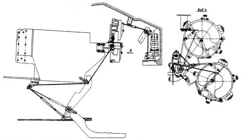
Catching mechanism
For firing from the cannon, shots of separate loading with a partially burning sleeve were used: 3VBM1 (with an armor-piercing sub-caliber projectile 3BM5); 3VBK4 (with the 3BK8 or 3BK8M cumulative projectile) and 3VOF18 (with the 3OF17 high-explosive fragmentation projectile). The maximum aiming range with the TPD-43 rangefinder sight for the 3BM5 projectile was 4000 m, for the 3BK8 (3BK8M) and 3OF17 projectiles - 3300 m, using the TPN-1 night sight - 800 m. m) was equal to 1870, 970 and 990 m, respectively. The armor penetration of the 3BK8M projectile was 450 mm, and the 3BM5 projectile at a distance of 1000 m was 250 mm (135 mm at an angle of 60 ° from the vertical).
To increase the rate of fire of the gun, the tank was equipped with a conveyor-type electrohydromechanical loading mechanism (MH). For loading, the gun was brought to a constant elevation angle of 2 ° 48 '. The structure of the MH included: a conveyor, a conveyor turning mechanism, a feeding mechanism, a mechanism for catching and shifting a pallet, a chambering mechanism, hydraulic and hydraulic distributing devices, a hydraulic stop for a gun, a hydraulic stop for a conveyor rotation mechanism, a relay block for a loading mechanism, a control panel, a loading and unloading panel for shots. The speed of rotation of the conveyor was 24 deg / s, the minimum duration of loading one shot was 6 s, the maximum (full turn of the conveyor) was 20 s.
The conveyor was a welded ring structure that was placed outside the cabin. With its upper ring, it was attached to the inner crown of the shoulder strap of the tower support and rotated on a ball support. The conveyor contained 30 trays of the loading mechanism with shots, which were brought out to the loading line using the conveyor rotation mechanism (the hydraulic motor of the mechanism was located to the right of the commander's seat) and the feed mechanism lever. The ramming of the shot into the chamber of the gun barrel after its output to the loading line was provided by a ramming mechanism with a reversible hydraulic motor installed on the bottom sheet in the rear of the tower. The retention of the gun at the loading angle during the operation of the feed and ramming mechanisms was ensured by a hydromechanical stopper attached to the right side of the cannon in front of the roof of the tank turret.
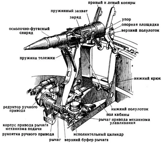
Loading mechanism tray with a high-explosive fragmentation round on the ramming line
After the shot was fired, the extracted pallet (the metal part of the partially burning sleeve) was captured and held by a cable-driven catching mechanism (mounted on the rear of the left shield of the cannon guard), which, after the next loading of the gun, transferred it to the freed conveyor tray. Combat rate of fire using the loading mechanism reached 8-9 rds / min.
In the event of a failure of the MZ, loading the gun with shots from the conveyor could be carried out using manual (duplicate) MZ drives (turning the conveyor and lifting the lever of the feed mechanism). For this purpose, a special removable handle was used, which was installed on the shank of the gear of the manual drive of the feed mechanism (three-stage cylindrical gearbox). The cannon could also be loaded manually with shots taken from the tank's non-mechanized ammunition racks.
The gun ammunition consisted of 40 shots, 30 of which were located in the trays of the MZ conveyor, where they were stacked in three types in any ratio. The remaining ten shots only with high-explosive or cumulative shells were placed in non-mechanized rack stacks in the control compartment and in the fighting compartment. In the control compartment there were six charges and eight shells, of which four charges and eight shells were placed in special slots in the storage tank, and two charges were installed vertically near it and held with clamps. The fighting compartment housed four charges and two shells. Three charges were located in front of the commander's seat on the cockpit floor: one charge and one projectile each - in the left niche of the turret and one projectile - behind the tank commander's seat.
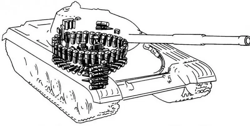
Placement of ammunition in the tank "Object 432"
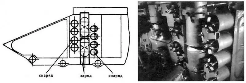
Stowage of ammunition (in the rack tank) in the control compartment of the tank "Object 432"
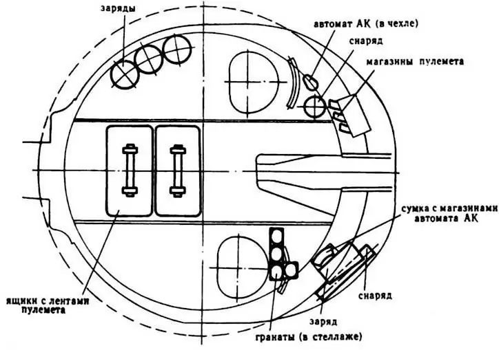
[center] [center] Stowage of ammunition in the cockpit and turret of the Object 432 tank
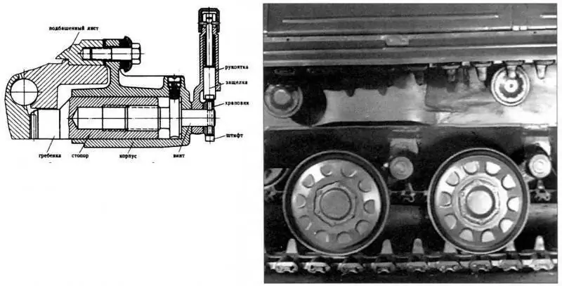
Ridge stopper of the "Object 432" tank turret.
Ammunition for the PKT coaxial machine gun consisted of 2000 rounds. Machine-gun cartridges were loaded in belts of 250 pieces. and were placed as follows: one tape in the store - on the mount of the machine gun; three ribbons in three stores - in the right niche of the stern of the tower; four tapes in two boxes - on the cockpit floor under the cannon.
Inside the tank, stowage was also provided: for the AK-47 assault rifle (mounted in a case in the fighting compartment on the wall of the cockpit behind the commander's seat) with 120 rounds, a 26-mm SPSh signal pistol (in a holster on the left removable cockpit shield behind the gunner's seat) with 12 signal cartridges and 10 F-1 hand grenades with fuses (in four bags on the cockpit floor behind the gunner's seat).
In the stowed position, the gun was stopped using a special thrust, which made it possible to fix it relative to the tower in one of three vertical positions. Stopping the turret relative to the tank hull in any position was provided by a turret ridge stopper with eight teeth. To prevent the electric drive from turning on when the tower was locked, there was a blocking of the electric drive with a tower stopper.
Armor protection of the tank - anti-cannon, using combined armor barriers in the structure of the hull and turret. It provided protection for the crew and internal equipment from the effects of all types of projectiles of foreign 105-mm rifled tank guns from a range of 500 m at course angles of fire ± 20 °.
The frontal and zygomatic armor plates of the bow of the hull had large angles of inclination from the vertical. The angle of inclination of the upper frontal part of the hull, which had a multi-layer combined structure, was 68 ° from the vertical. Between the outer and inner armor plates were two sheets of fiberglass. This relatively light material, without causing a large increase in the mass of the tank hull, effectively weakened the effect of the cumulative jet and the flux of fast neutrons.
Two towing hooks with spring latches, two brackets with guards for attaching headlights and tubes for supplying electrical wires to headlights and side lights, two brackets for attaching tow cables were welded to the upper inclined sheet. A mud deflector was attached to the headlight brackets, preventing water and dirt from flowing onto the hull when the tank was moving.
The sides of the hull are vertical armor plates, which had a stamping in the middle part, made to increase the internal volume of the hull (for the installation of the MZ with the placement of the maximum possible number of shots). In the upper part of each stamping there were two local recesses: under the upper branch of the caterpillar and under the welding of the turret armor plate. In addition, brackets of the idler cranks (in the front), four brackets of the carrier rollers (along the middle part), balancer stops (one at the front and two at the fifth and sixth suspension nodes), axles for fastening were welded to the sides of the hull from the outside. shock absorbers on the first, second and sixth suspension nodes, as well as fenders with dust and mud flaps (front and rear). In the places where the shock absorbers were installed, recesses were made in the sides of the hull, which, together with the recesses for the upper branches of the tracks, formed weakened zones of armor protection.
The stern part of the hull was a welded assembly of stamped armored stern plate, an inclined part of the rear bottom plate and gearbox housings welded to the sides. On the stern sheet on the left and right in its upper part, one bracket was welded for attaching the rear marker lights, in the middle part - brackets for the self-pulling log attachment bands, as well as brackets for attaching the louvers at the engine exhaust gas outlet from the ejector, in the lower part, closer to gearbox housings - towing hooks with spring latches. In the middle of the stern sheet there was a hole for the installation of an adjusting screw for twisting the torsion bars of the MTO roof, which was closed with a protective cylindrical cap.

The scheme of armor protection of the tank "Object 432" produced in the first half of 1964.
The hull roof consisted of front and rear armor plates, a removable part of the roof over the MTO and two armored turret pads. In the front sheet of the roof along the longitudinal axis of the hull there was a cutout for the driver's entrance hatch, to the right of it there was a hatch for refueling the front fuel tanks, to the left there was an air intake hatch. On the back sheet of the roof, on the left side of the side, there was a hatch for ejecting water with a stern pump, a hatch for refueling the rear fuel tanks, and a pipe was welded to connect the outer fuel tanks to the inner ones. On the right side of the side were the air intake hatch of the supercharger and the hatch for the discharge of separated dust. To protect them, bulletproof strips were welded.
The welded structure of the MTO roof was made of rolled armor plates and cast sidewalls, on the inside of which an ejector box was welded. In the front part of the removable roof there were blinds above the radiators, on the left at the side - blinds above the air cleaner. All the blinds were covered with safety nets. In addition, on the roof of the MTO there were hatches for refueling the oil tanks of the engine, transmission and cooling system, as well as hatches for installing a valve when driving a tank underwater and for installing an exhaust system receiver and louvers for the bypass duct of the gas duct. In the cavity of the removable roof there was a hatch for intake of compressor cooling air. All hatches were closed with armored covers.
To provide access to the components and assemblies of the power plant and transmission, the roof was raised to an angle of 29 ° 30 using a lever-torsion lifting mechanism.
The bottom of the tank hull was welded from three stamped armor plates, which had a trough-shaped cross-section. For compact placement of torsion bars and increasing the rigidity of the structure, longitudinal and transverse stampings were made in the bottom. In the front sheet of the bottom there was also a stamping, which provided the necessary height to accommodate the driver in combat. Six brackets of suspension assemblies were welded along the sides of the hull in the bottom on each side. In the bracket of the sixth suspension unit on the left side there was a hatch for the release of combustion products from the heater, which was closed by an armored cover. Opposite the brackets along the longitudinal axis of the body, six torsion shaft supports were welded into the cutouts in the bottom. In the bottom of the hull there were also hatches, which were closed with armored plugs and covers and intended for access to the units and assemblies of the tank during its maintenance. Two round holes were made in the MTO partition: in the right part, at the bottom at the side - for the outlet of the heater boiler flame tube, in the upper left part - for welding the flange for installing the fan. In addition, the baffle contained holes with guide bushings and seals (to ensure the required tightness) for the passage of control drives, pipelines and electric wires.
The turret of the tank was a shaped casting of armored steel with a powerful frontal part, to the upper part of which a stamped roof and the body of the base tube of the rangefinder sight were welded, and a bottom sheet in the groove of the lower part. In the right and left halves of the frontal part of the turret, there were special cavities filled with aluminum alloy inserts. In front of the tower there was an embrasure with a closed perimeter for installing a cannon. Arc cheeks were welded to the side surfaces of the embrasure, intended to protect the inner cover from the lead splashes of bullets, sealing the gun embrasure, and to reduce the pressure of the passing shock wave acting on the cover. In the upper part of the embrasure, an upper protective shield was attached to the welded strips. To fasten the outer cover of the gun, grooves were welded on top and on the sides of the embrasure, and at the bottom of the embrasure - a bar with holes for bolts. To the right of the embrasure was an oval hole for a coaxial machine gun, on the left a bracket was welded for installing an L-2AG searchlight and a tube for supplying an electric wire to it. There were special cutouts in the tower body in front of the exit windows of the rangefinder sight, which provided the necessary visibility.

Tank tower "Object 432"
In the right half of the roof of the tower there was a round hole into which the antenna mounting flange was welded, and behind it was a cutout for welding the base of the commander's cupola to the tower.
In the left half of the roof, two round holes were made for attaching the rangefinder sight rod and the gunner's observation device, as well as two semicircular cutouts. The flange for mounting the TPN-1 sight and the base of the gunner's hatch were welded into the cutouts. In the upper part of the stern of the tower there was a threaded hole for attaching a socket for communication with the landing party, two fasteners for attaching the headlight pipe and an opening for the output of an electric wire to it, as well as a turret air intake hatch.
The tower was mounted on a ball bearing, which was an angular contact bearing with a covered movable shoulder strap, touching the balls with treadmills at two points. The upper shoulder strap of the tower support was bolted with shock-absorbing (rubber) bushings to its bottom sheet, the lower one - in the annular groove of the front and rear hull roof sheets, and turret strips. The joint of the lower shoulder strap with the roof parts was sealed with a rubber ring. Between the turret and the lower shoulder strap in the groove of the lower shoulder strap, a rubber cuff was installed, tightened with a nylon ring, which prevented dust from entering the fighting compartment when the tank was moving, water during underwater driving, a shock wave and radioactive dust in a nuclear explosion.
For the installation and dismantling of the tower, two hooks were welded in its front and rear parts, and one landing handrail was welded on the sides of the tower. In addition, in the aft part of the tower there were brackets, brackets, brackets for fastening tarpaulins, covers for sealing the louvers over the air cleaner and the L-2AG floodlight, as well as hooks for attaching the OPVT pipe discharge cable for exhausting engine exhaust gases.
The tank was equipped with a PAZ system, which, together with an armored structure and permanently installed sealing devices, protected the crew and internal equipment from the impact of the shock wave of a nuclear explosion due to additional sealing of the vehicle with automatic closing of all openings (ventilation hatches, louvers over the radiator and air cleaner, gas duct flaps and ejector box, blower valves). Permanent seals had: cannon and machine gun embrasures, turret ball bearing, MTO bulkhead, crew hatch covers and an emergency exit, as well as installation sites for observation and aiming devices.
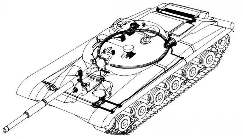
Placement of the PAZ system equipment in the "Object 432" tank

Sealing the embrasure of the cannon of the Object 432 tank. Center - Sealing the PKT coaxial machine gun of the Object 432 tank. Right - Mechanism for closing the air intake hatch of the driver.
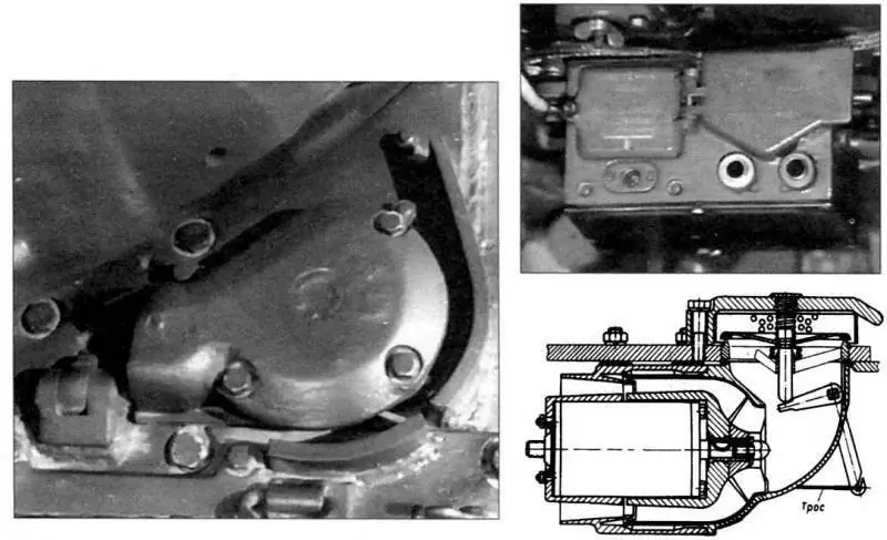
Armor protection of the tank supercharger "Object 432". Right, top - Automatic machine of the AS-2 UA PPO system, installed in the control compartment on the upper frontal sheet of the hull. Right, bottom - Installation of a supercharger in the Object 432 tank.
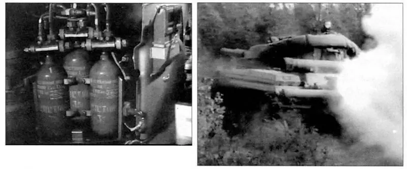
Installation of cylinders with fire extinguishing composition "3, 5" of the UA PPO system in the fighting compartment behind the rack with batteries. Right - Setting up a smoke screen by the Object 432 tank using the TDA system.
Protection against fast neutrons was provided by installing a special anti-radiation material (lining) based on polyethylene inside the machine. Additional protection for the commander and gunner was also vertically located artillery rounds, and for the driver - diesel fuel, located in the left and right front tanks. All this provided a 16-fold reduction in the level of penetrating radiation. In addition, a "falling" seat was introduced to protect the tank commander. When the PP-3 squib of a special mechanism was triggered, the seat, together with the commander, dropped down under the protection of the thickest armor of the tower.
To protect the crew from radioactive dust when the tank overcomes areas of radioactively contaminated terrain, it was envisaged to supply purified air with a supercharger to the fighting compartment and create overpressure (backwater) inside the manned compartments, which prevents dust from penetrating through the leaks of the hull and turret of the vehicle. The blower was a centrifugal fan with inertial cleaning of dusty air in the rotor. It ensured the creation of an overpressure of at least 0.29 kPa (0.003 kgf / cm2) and air purification from dust by about 98%.
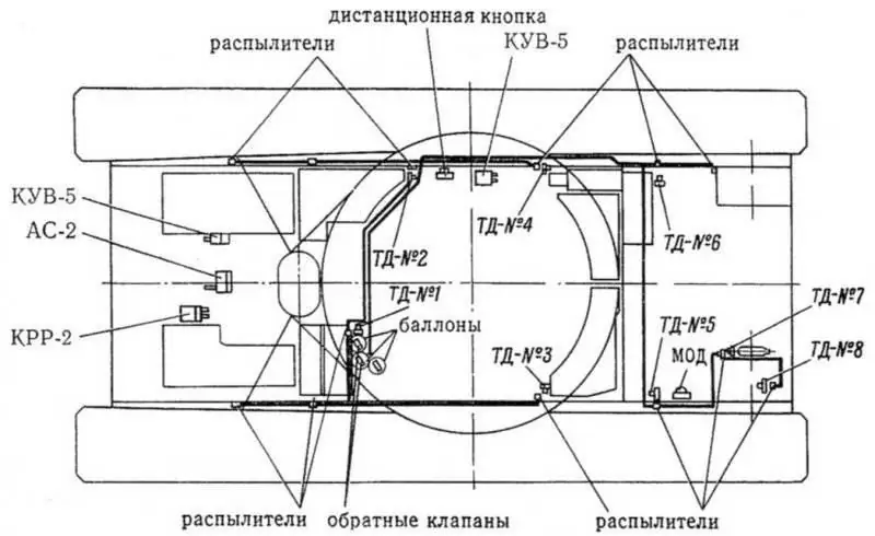
Layout of the equipment of the UA PPO system in the "Object 432" tank
In addition to the specified equipment, the PAZ system included a radiometric protection unit RBZ-1M, an X-ray meter DP-3B, MOD, as well as electrical equipment of the system (electric motor of the MV-67 blower, fan and blower control box KUV-5, electromagnet MOD, fuses of the pyrocartridges of the closing mechanisms PP -3, etc.).
Extinguishing the fire that broke out in the tank was carried out using a three-time UA PPO system, which could operate in automatic, semi-automatic or manual modes. The system consisted of: an automatic machine of the AS-2 system, a relay-distribution box KRR-2, two boxes KUV-5 for controlling a fan and a blower, eight TD-1 temperature sensors with nozzles, as well as three two-liter cylinders with the composition "3, 5", two pipelines, four check valves, a remote button (in the fighting compartment of the tank commander), an electric drive and a mod. To extinguish minor fires, there was an OU-2 manual fire extinguisher (attached behind the seat of the tank commander on board the cockpit).
For setting up smoke screens in order to camouflage the tank, it was equipped with a multiple-action TDA system. The smoke vent was allowed to be turned on only when the car was moving and the engine was well warmed up.
The basis of the power plant of the tank was a 5TDF two-stroke high-speed diesel engine with a power of 515 kW (700 hp) at a crankshaft speed of 3000 min-1. The engine was attached at three points with two rigidly fixed trunnions and one pivot bearing. The installation of the engine did not require alignment and adjustment with respect to the transmission units. The engine was started using an SG-10 starter-generator with a power of 10 kW (main method) or using compressed air from two five-liter air cylinders (backup method). The cylinders were charged from the AK-150S compressor, which was driven by the engine. If necessary, the engine could be started in a combined way (simultaneously with a starter-generator and an air release) or from a tug.

Diagram of the air start system of the engine of the tank "Object 432". Center - Cooling and heating system of the tank "Object 432". Right - Air cleaning system of the engine of the tank "Object 432".
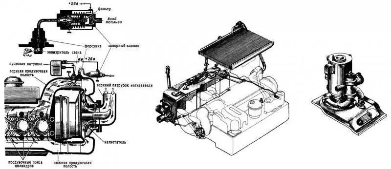
Electric torch heater of the inlet air of the tank engine "Object 432". Center - Lubrication system of the engine of the tank "Object 432". On the right is a centrifugal bilge pump with a switching valve used to fill the fuel tanks of the Object 432 tank with fuel. Lubrication system of the engine of the tank "Object 432".
To warm up the power plant before starting the engine and maintain it in a state of constant readiness for starting at low ambient temperatures, a heating system was used, combined with the engine cooling system. The heating system consisted of a small-sized nozzle heater, a flame tube of the oil tank, water jackets of the engine and oil-injection pump MZN-2, a fuel switch and pipelines. When the heater was turned on, the engine and the power plant units were warmed up
heated liquid, and the oils in the oil tank - by the exhaust gases of the heater. In addition, to facilitate starting the engine, the air entering the engine cylinders was heated using electric torch heating (the electric torch heating switch was installed on the driver's instrument panel). To heat the air in the fighting compartment of the tank in winter, a heater (air heater) of the fighting compartment was used, which was installed on the heater boiler bracket and made a single unit with the heater. The heater was turned on with the "Heating B / O" switch on the driver's instrument panel.
The capacity of the main (internal) fuel tanks was 815 liters (left front - 170 liters, right front - 165 liters, storage tank - 170 liters, rear left - 178 liters, rear right - 132 liters), additional (three fuel tanks on the left fenders) - 330 liters. The front fuel tanks and the storage tank made up the front group of tanks, the rear fuel tanks and the outer ones - the rear group of tanks. In this case, the external fuel tanks could be disconnected from the rear internal tanks using a tap on the front wall of the left rear fuel tank. Internal fuel tanks were welded from stamped steel sheets and covered with bakelite varnish inside; the outer fuel tanks were aluminum.
Fuel production was primarily carried out from external tanks (connected in series) and was carried out through the rear tank, the pipeline of which was connected to the shut-off valve of the external tanks. The development of fuel from the front group of tanks was allowed in the last turn due to the need to provide anti-radiation protection for the driver.
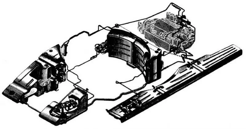
Fuel system of the engine of the tank "Object 432"
Refueling of tanks with stationary and mobile special refueling means was carried out with a closed jet of fuel. In this case, the front group of tanks was filled with fuel through the neck of the rack tank, the inner tanks of the rear group - through the filler neck of the left rear tank, external fuel tanks - through their filler necks.
To refuel the tank's fuel tanks, a refueling device could also be used, which consisted of a bow centrifugal bilge pump, a switch valve ("water" - "fuel"), a refueling fuel filter and a removable refueling device that was lowered into a container with fuel. The tank's power reserve on the highway at one gas station reached 550-650 km.
In the air cleaning system, a single-stage cassette-free cyclone-type air cleaner (145 cyclones of a horizontal arrangement) with ejection dust removal from a dust collector was used, which was installed in the MTO at the left side. As shown by the operation, it did not provide the proper degree of air purification, which was one of the reasons for the failure of the 5TDF engine before the specified resource was used up.
In the forced lubrication system of the engine (the filling capacity of the system is 75 l) with a dry sump, a full-flow fine oil centrifugal filter was used, which was attached to the top of the engine block. A continuous supply of oil to the rubbing parts was provided by a pressure oil pump. To create a given pressure in the system in a wide range of changes in the speed of the engine crankshafts, the capacity of the injection oil pump was 120 l / min.
The engine cooling system is a liquid, closed type, with forced circulation of the coolant and ejection suction of cooling air through the radiators. The use of an ejection cooling system in the air path ensured the compactness of the cooling system, its good self-regulation and a decrease in the amount of heat emitted by the tank. The filling capacity of the cooling system was 65 liters. Two series-connected and similar in design tubular-plate radiators were installed in the same plane in an ejector body isolated from the MTO with an angle of inclination to the horizon of 4 ° towards the nose of the tank. The slope of the radiators ensured complete drainage of the coolant from the system.
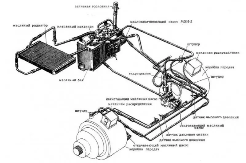
Scheme of lubrication and hydraulic control of the transmission of the tank "Object 432"

Ejector of the engine cooling system of the tank "Object 432". Center - Transmission unit (right) of the Object 432 tank. On the right - the final drive and the drive wheel with non-removable gear rims of the 432 Object tank.
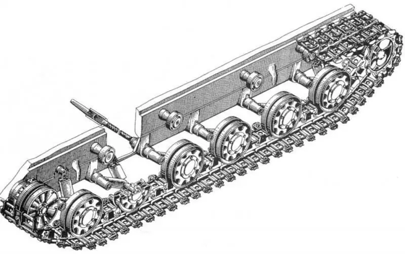
The chassis of the tank "Object 432"
The mechanical planetary transmission consisted of two BKPs (left and right), two planetary final drives and a lubrication system combined with a hydraulic servo control system. The transmission provided a high average speed, good maneuverability and maneuverability of the tank. Its high efficiency contributed to obtaining a large power reserve, and the use of a hydraulic transmission control system greatly facilitated the control of the movement of the tank. Changing the speed of movement and tractive effort, turns, braking and turning off the engine were made by turning on and off certain friction devices in the BKP. The principle of turning the tank was to change the speed of rotation of one of the tracks by switching on the gear one step lower in the BKP from the side of the lagging side.
Planetary BKP with three degrees of freedom and with friction elements operating in oil, provided seven forward gears and one reverse gear. Left and right BKP were not interchangeable. The final drive (left and right) was a planetary coaxial reduction gear of an unloaded type (i = 5, 454). Each BKP was rigidly connected to the final drive and constituted the transmission unit. The transmission of torque from the engine to the drive shafts of the BKP was carried out using gear couplings. The average speed of the tank on dirt roads reached 40-45 km / h.
The hydraulic servo control system for transmission units included hydraulic servo drives from the transmission pedal and steering levers, which functioned according to the pressure regulator principle, and a hydraulic servo drive from the gear selector lever, which worked according to the “On / Off” principle. The stopping brakes are driven mechanically, with a servo mechanism.
In the chassis, the suspension system used an individual torsion bar suspension with coaxial torsion shafts and double-acting piston hydraulic shock absorbers on the first, second and sixth suspension units, as well as rigid stops for the first, fifth and sixth suspension units. The shafts of the left and right suspension assemblies were not interchangeable.
The tracked propeller consisted of two leading lantern gearwheels with caterpillars, two cast guide wheels with crank worm mechanisms for tensioning the tracks, 12 double support and eight single-band support rollers with internal shock absorption, as well as two small-link tracks with parallel type RMSh.
The drive wheels had cast hubs, to which gear rims were welded, which had tides that limited the lateral movement of the tracks on the drive wheel and did not allow the caterpillar to be dropped. In addition, to prevent the track from dropping from the drive wheel towards the side, two bumpers were welded on the rear of the hull. To clean the drive wheels from dirt and snow, mud cleaners were attached to the brackets of the travel limiters of the balancers of the rear road rollers.
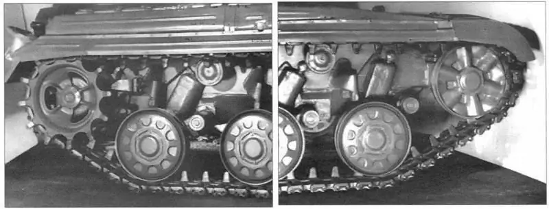
View of the drive wheel with non-removable toothed rims, the drive wheel dirt cleaner, the travel stop of the sixth road roller, support and support rollers with internal shock absorption and a telescopic shock absorber on the starboard side of the Object 432 tank. On the right - View of the all-metal idler wheel, travel stop of the first road roller, support and support rollers and telescopic shock absorbers on the starboard side of the Object 432 tank.
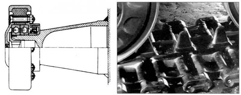
Carrier roller with internal depreciation of the Object 432 tank. On the right - Track links of the tracks from the RMSh of the tank "Object 432".
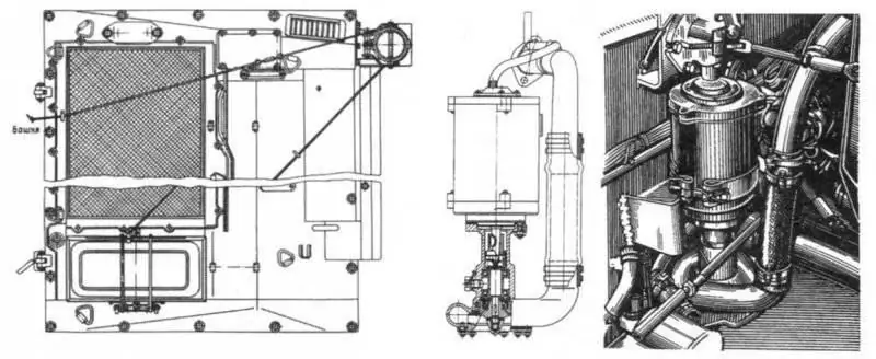
Installation of a louver seal over the air cleaner and a mechanism for dumping the exhaust pipe from the OPVT set of the 432 Object tank. On the right - a stern centrifugal bilge pump and its installation in the MTO tank "Object 432".
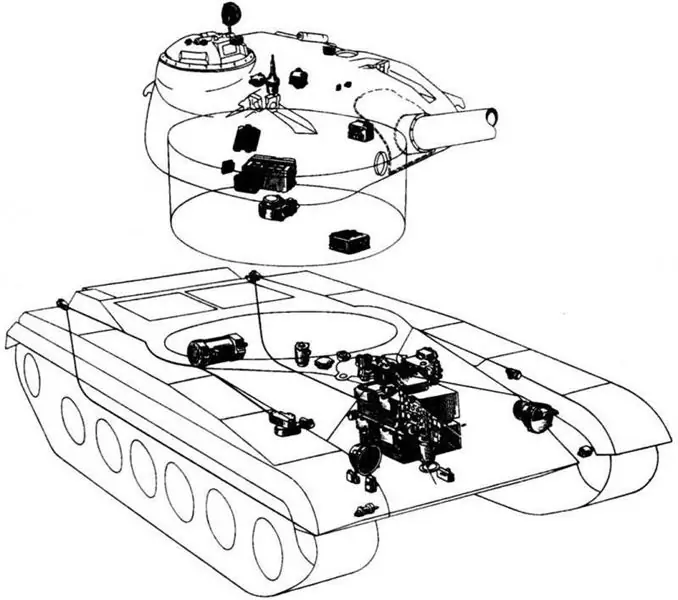
Placement of electrical equipment in the tower and in the hull of the tank "Object 432"
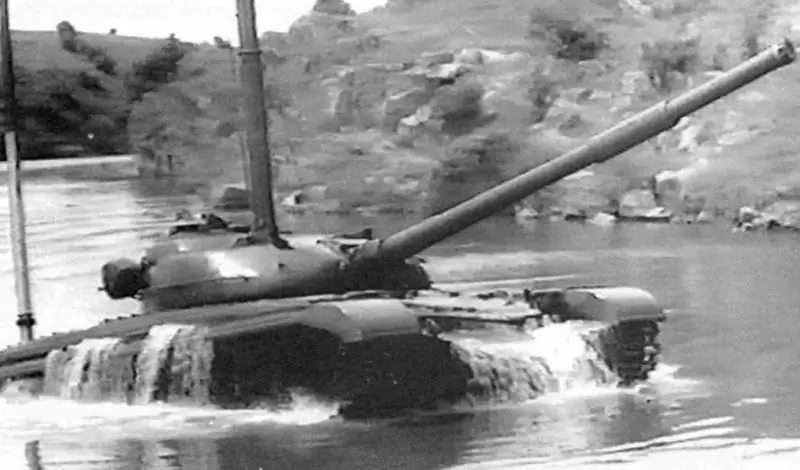
Overcoming the tank "Object 432" water obstacle with installed OPVT
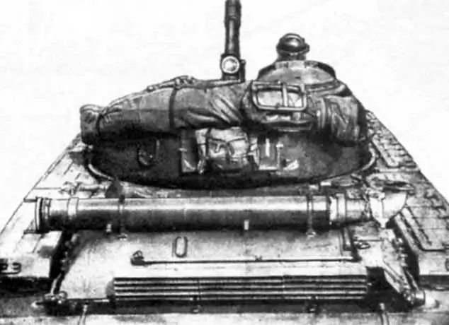
Placement of the detachable part of the OPVT set on the tower and the roof of the MTO tank "Object 432" for transportation
Steel double-disc cast box-shaped guide wheels were installed on the short axes of the crank mechanisms of the caterpillar tensioning mechanism with a globoid worm gear. The left and right track tensioners were not interchangeable. A gearbox with a tachogenerator was mounted in the right tensioning mechanism, and a gearbox with an electro-speedometer sensor was mounted in the left one.
Each track roller consisted of a steel hub, a stamped steel rim (welded in two halves), two outer discs (to reduce weight, the discs were made of an aluminum alloy) with vulcanized rubber rings (shock absorbers) and a coupling nut. On the inside of the track roller, a labyrinth seal washer was welded to the hub along the perimeter. In order to increase the strength, the rims of the track rollers were specially processed by knurling with a roller to form an outer layer of "work hardening". On the axis of the balancer, the support roller was installed on a double-row tapered unregulated bearing, which was locked on the axis with a nut and was closed from the outside by an armored cover.
The carrier roller consisted of a steel rim and a rubber ring (shock absorber) vulcanized from the inside. The ring had eight holes for the pins of the cover bolts, in the bores of which two ball bearings were installed when the roller was mounted on the bracket axis.
Caterpillars 540 mm wide were assembled from 78 tracks each. The track of the caterpillar consisted of two stamped steel links and two fingers with rubber rings vulcanized on them. The tracks were connected to each other using two brackets, a ridge, a shoe, two locking wedges and four bolts, stopping from spontaneous loosening by riveting the bolt (option 1) or punching the headrest of the bolt (option 2). The average ground pressure was 0.079 MPa (0.79 kgf / cm2).
The electrical equipment of the machine was made according to a single-wire scheme, except for the emergency lighting. The rated voltage of the on-board network was 24-28.5 V (in the starting mode - 48 V). The sources of electricity were four 12ST-70M starter batteries with a total capacity of 280 Ah and an SG-10 starter-generator with a capacity of 10 kW when operating in generator mode. The switching of the batteries from 24 to 48 V and back into the electric circuit of the starter-generator when the engine was started was carried out by the RSG-10M relay.
The consumers of electrical energy included: the SG-10 starter-generator when operating in the starter mode; weapon stabilizer; loading mechanism; electric motors of an exhaust fan, a blower for the driver, oil pumps for the engine and tug, water pumps, a heater and heating for the crew compartment and TPD; night observation devices; viewing device heaters; lighting and light signaling devices; sound signal; heading indicator; PAZ and UA PPO systems; means of communication; starting coil and spark plug, etc.
For external radio communication, the tank used an ultra-short-wave tank radio station R-123 (located in the fighting compartment in front to the right of the commander), and for internal communication - TPU R-124.
To overcome water obstacles along the bottom of the reservoir up to 5 m deep, the Object 432 tank was equipped with an OPVT, which included removable and permanently installed units. The latter included the hull and turret seals, gun armor protection, exhaust gas bypass flaps, drives to the gas duct damper and to the air cleaner ejector seal valve, two bilge pumps (each with a capacity of 100 l / min), a gyrocompass and electrical equipment. The OPVT set also included three AT-1 isolation apparatus, which were stored in the tank.
When preparing the tank for overcoming a water obstacle, it was additionally mounted: an air supply pipe, an engine exhaust pipe (exhaust), an exhaust valve, a louver seal over the air cleaner, an air cleaner ejector seal, a MTO ventilation hole seal, a gun muzzle seal, a coaxial machine gun seal, a valve for draining water from a gas duct, check valves for water pumps, clips for fixing the handle of the blind drive backstage. It took the crew 45 minutes to install this equipment. The movement of the car along the bottom of the reservoir was carried out in 1st gear. Maintaining a given direction of movement was ensured with the help of the GPK-59 gyrocompass and radio communication with the head of the crossing on the shore.
After crossing the water barrier, the time required to prepare the tank for immediate firing was only 1 minute.
Under normal operating conditions, removable OPVT units were laid and attached to the outside of the tank in established places.
During production in 1964-1965. tank "Object 432" was continuously undergoing modernization aimed at improving the reliability and increasing the service life of its main components and assemblies, as well as combat and technical characteristics. Here are the main measures being implemented.
By armament:
- exclusion of the "subsidence" of the gun and its sticking into the ground;
- improvement and refinement of the design of the stabilizer of the main weapon "Lilac";
- introduction of a scale for a high-explosive fragmentation projectile in the TPD-43 rangefinder sight;
- increasing the reliability of the loading mechanism (excluding the non-catching of the pallet and its jamming in the catcher, the pallet falling out of the trap, as well as the fuzzy operation of blocking the chambering chain);
- reducing the dustiness of the loading mechanism;
- increasing the strength of the trays of the loading mechanism;
- elimination of ammunition counter failures;
- changing the ventilation system of the fighting compartment.

General view of the tank "Object 432" produced in September 1964
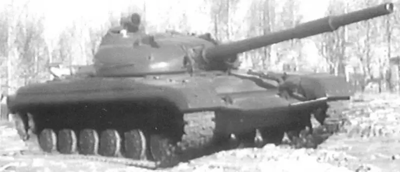
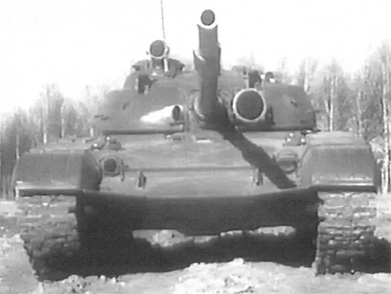
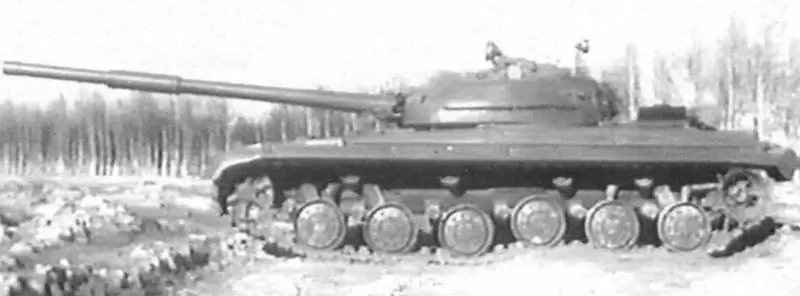
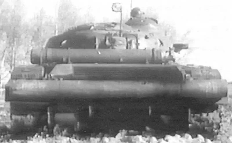
Tank "Object 432" release from September 1964
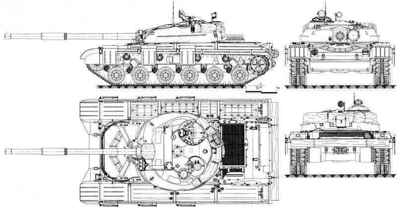
General view of the tank "Object 432" produced in 1965
For armor protection:
- increased armor protection (excluding the ricochet of shells into the turret when firing at the vehicle) due to the introduction of an armor plate on the upper frontal sheet of the hull (from July 1964) and on the cheekbones of the roof of the control compartment, the so-called "eyebrows" (from September 1964 onwards).);
- the introduction of armor plates to strengthen the front part of the stamping of the sides of the hull (from July 1964);
- installation of anti-cumulative shields (screens) since 1965 (mounted on a tank only in combat conditions). Three right and three left side flaps (swivel) were attached to the corresponding fenders in the front of the tank, the front (left and right) flaps - on the front folding mud flaps, and the rear flaps (left and right) - on the front dust flaps mounted on fenders. In the working (combat) position, the rotary side flaps were installed at an angle of about 70-75 ° to the fenders of the tank.
By engine:
- increasing the reliability of the blower, ratchet clutch, fuel supply equipment, water pump seals and other units and assemblies;
- ensuring reliable engine start-up at low ambient temperatures;
- an increase in the service life of the engine from 150 to 300 h;
- improvement of the air cleaning system;
- improving the reliability of the heater operation at low ambient temperatures;
- reduction in oil and fuel consumption (exceeded the specified one by 20-30%).
By transmission:
- improving the reliability of the BKP (for friction elements F2, F6 and F6);
- improved sealing of final drives.
On the chassis:
- elimination of damage to the drive wheel teeth and the transition to removable gear rims (from the second half of 1964);
- increasing the reliability of the road wheels (eliminating the destruction of rubber shock absorbers and steel rims) and the wear resistance of the carrier wheel rims;
- reduction of the track track wear (elimination of cracks in brackets and breakage of bolts and pins);
- exclusion of tracks falling off the drive wheels, overheating of hydraulic shock absorbers and breakdowns of torsion shafts and tearing of their supports (1, 5 and 6).
In addition, a number of measures were carried out on the UA PPO system, if possible, the driver's transition from the control compartment to the combat one at any position of the tower, as well as to increase the ford depth, overcome without preliminary preparation of the machine.
For a more convenient location of the landing on the sides of the tower, instead of one, they began to install two handrails.
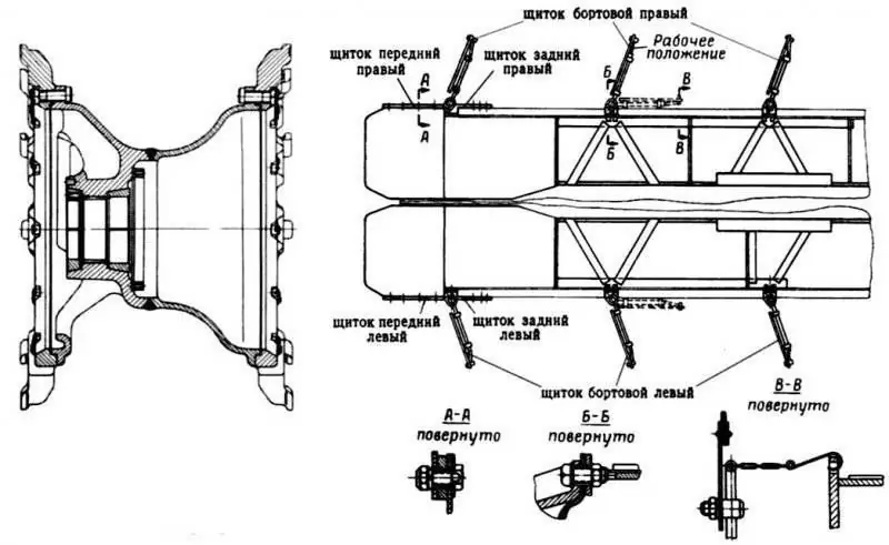
The design of the drive wheel with removable gear rims of the tank "Object 432". Right - Scheme of installation of on-board anti-cumulative shields (screens) on the "Object 432" tank.
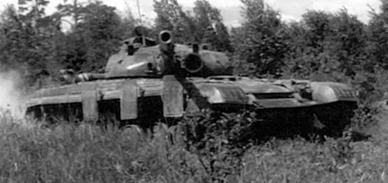
Tank "Object 432" with anti-cumulative shields (screens) installed in the stowed position
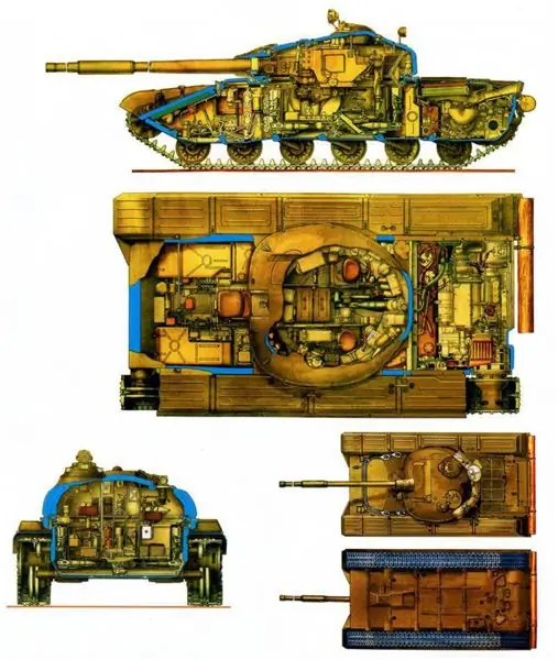
Tank "Object 432" produced in 1964. Fig. A. Shepsa

Tank "Object 432" on military trials. 1964-1965 Rice. A. Shepsa


