- Author Matthew Elmers elmers@military-review.com.
- Public 2023-12-16 21:49.
- Last modified 2025-01-24 09:17.
Until recently, this ship was considered very little known. Not so many sources wrote about this machine - a kind of one of its kind.
But until now, the LRV project is striking in its sophistication, which favorably distinguishes it from other projects of military spaceships (for the most part, they were nothing more than sketch drawings)

It all began in 1959 at NASA, when, during the discussion of the development program for a maneuverable (capable of controllably de-orbiting) spacecraft, a disc-shaped shape was proposed as the most satisfying the requirements of thermal stability. When analyzing, it turned out that a disk-shaped apparatus would be more advantageous in terms of thermal protection than a conventional design.
North American Aviation took over the development of the program at Wright-Patterson Air Force Base from 1959 to 1963.
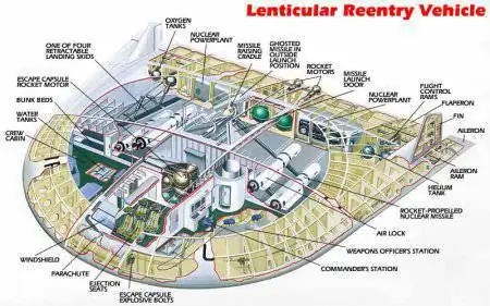
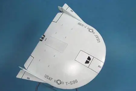
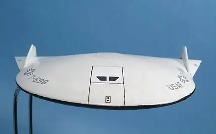
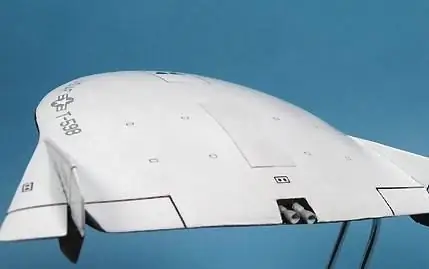
The result of the program was a disk-shaped aircraft with a diameter of about 12.2 meters with a center height of 2.29 meters. The weight of the empty vehicle was 7730 kg, the maximum weight of the spacecraft launched into orbit was 20 411 kg, the payload weight was 12 681 kg, including the weight of the missiles - 3650 kg. The apparatus housed: a rescue capsule, a living compartment, a working compartment, an armament compartment, the main propulsion system, a power plant, oxygen and helium tanks. On the trailing edge of the LRV, vertical and horizontal control surfaces were located, with the help of which, after de-orbit, a controlled descent in the atmosphere was carried out. The aircraft-type landing was carried out on a retractable four-post ski landing gear.
By its design, the LRV was supposed to become an orbital bomber, a means of delivering a first and disarming strike against the enemy. It was assumed that on the eve of the conflict, this combat vehicle will be launched into orbit using a Saturn C-3 rocket. Having the ability to stay in orbit for up to 7 weeks, the LRV could patrol for a long time, in full readiness for an attack.
In the event of a conflict, the LRV had to reduce the altitude of the orbit, and attack the target with 4 nuclear missiles. Each rocket had a supply of fuel to de-orbit the LRV and attack a ground object. It was assumed that the LRV could launch an attack faster than any other attacking weapon in the US arsenal, and at the same time, the enemy would have little time to react.
The advantages of the project were the excellent security of the LRV. By 1959, ballistic missile submarines were still forced to approach the enemy coast. LRV, on the other hand, could attack anywhere on the planet, remaining completely safe - it would be very difficult for missiles operating from the surface to attack it due to the high maneuverability of the apparatus.
It was assumed that the LRV will operate in conjunction with the orbital interceptor Dyna Soar. The interceptors were supposed to ensure the destruction of the enemy's satellite and anti-satellite systems, after which the LRV would attack.
Among the advantages of the project was the highest degree of ensuring the survival of the crew. The LRV, due to its controlled descent, was much more promising than the Gemini.
In case of impossibility of descent from orbit, the LRV design provided for a unique element - a maneuvering landing capsule that could save the crew.

Technical description of the LRV ship:
The LRV apparatus was structured as follows. The crew during the launch of the vehicle into orbit and its descent from orbit was to be located in a wedge-shaped capsule in the front of the vehicle. The purpose of the capsule is to control the LRV apparatus from it in a regular flight and to rescue the crew in case of an emergency during takeoff and landing. For this purpose, the capsule housed four seats for the crew members and a control panel, there were emergency life support systems and power supply. On top of the capsule there was a hatch through which the crew entered the capsule before launch. In an emergency, the separation of the capsule from the structure of the main apparatus was carried out by detonating the explosive bolts, after which a solid-propellant rocket engine with a thrust of about 23,000 kg, located in the rear of the capsule, entered into operation. The operation time of the emergency engine was 10 seconds, this was enough to take the capsule away from the abandoned vehicle to a safe distance, while the overload did not exceed 8.5 g. The stabilization of the capsule after separation from the main apparatus was carried out using four drop-down
tail surfaces. After the capsule was stabilized, its nose cone was dropped and the parachute located under it opened, providing a capsule descent speed of 7.6 m / s.
In normal LRV landing mode, i.e. when carrying out an aircraft landing, the nose cone of the capsule moved down and opened a flat slotted window, thereby providing an overview of the pilot. This nose window could also be used for forward viewing while the LRV was in orbit. To the right of the capsule was the living compartment for the crew, and to the left was the working compartment of the apparatus. These compartments were accessed through the side hatches of the capsule. The side hatches were sealed along the entire perimeter. During the emergency separation of the capsule from the main apparatus, the sealing devices were destroyed. The capsule length was 5.2 m, width - 1.8 m, empty weight - 1322 kg, estimated weight together with the crew in emergency landing mode - 1776 kg.
The living compartment was intended to rest the crew and maintain its physical condition at the required level. On the back wall of the compartment there were three bunk beds and a plumbing booth. The space at the bottom of the shelves was used to store personal belongings of the crew. Along the side, in front and on the right, there were exercise equipment for physical exercises, a storage and cooking unit, a table for eating. In the corner formed by the rear wall of the compartment and the right wall of the rescue capsule, there was a sealed airlock, which made it possible to exit the vehicle into open space or into the weapons compartment.
In the working compartment, located on the left side of the apparatus, there was a command console with communication and tracking equipment and a weapon operator's console, from which both missiles were launched and the unmanned satellite's weapons were remotely controlled. In the corner of the compartment there was also an airlock for going into outer space or into the weapons compartment. In the normal mode, the air pressure in the capsule, living and working compartments was maintained at 0.7 atmospheres so that the crew could work and rest without spacesuits.

The non-pressurized weapons compartment occupied almost the entire rear half of the LRV, its volume was sufficient both to store four missiles with nuclear warheads and for crew members to work in it in order to check and prepare missiles for launch. The rockets (two on the left and two on the right) were mounted on two parallel rails. A manipulator was located between the pairs of missiles along the longitudinal axis of the apparatus. Above it was a hatch through which, with the help of a manipulator, the missiles were alternately withdrawn and fixed on the back of the LRV in a combat position. All work on installing missiles in a combat position was carried out manually. In the event that the LRV, before the combat use of missiles, received an order to urgently return to the ground, the missiles were separated from the main vehicle and left in orbit for later use. The abandoned missiles could be launched remotely or picked up by other vehicles, and then used as usual.
The standard LRV kit also included a shuttle for two people. It was stored in the weapons bay and was intended to be visited by an unmanned satellite in order to maintain and repair it. To move in space, the shuttle had its own rocket engine with a thrust of 91 kg.
Nitrogen tetroxide N2O4 and hydrazine N2H4 were used as fuel for the main engine with a thrust of 907 kg, intended for maneuvering and deorbiting, for the shuttle engine and the engine of the unmanned satellite. In addition, the same fuel was used in the rocket engines of the unmanned satellite. The main fuel supply (4252 kg) was stored in LRV tanks, the fuel supply in the shuttle was 862 kg, in an unmanned satellite - 318 kg, in rockets - 91 kg. The shuttle refueled as the main apparatus used up its supply of fuel. The shuttle's fuel was used to refuel the tanks of the unmanned satellite during maintenance and repair work. The missile fuel systems in combat mode were permanently connected to the satellite tanks. If the missiles were fired or disconnected for maintenance or repair, then at the point of the connector, the pipelines were blocked by automatic valves to prevent fuel leakage. The total fuel leaks for six weeks on alert were estimated at 23 kg.

LRV had two separate power supply systems: one to ensure the operation of consumers during launching and descent from orbit, the other to ensure the normal operation of all systems of the vehicle during 6 weeks in orbit.
The power supply of the vehicle in the modes of launching into orbit and de-orbiting was carried out using silver-zinc batteries, which made it possible to maintain a peak load of 12 kW for 10 minutes and an average load of 7 kW for 2 hours. The weight of the battery was 91 kg, its volume did not exceed 0.03 m3… After the completion of the mission, it was planned to replace the spent battery with a new one.
The power plant for the orbital phase of the flight was developed in two versions: on the basis of a miniature source of atomic energy and on the basis of a solar energy concentrator of the "Sunflower" type. The total power of consumers during operation in orbit was 7 kW.
In the first version, it was necessary to provide reliable radiation protection for the crew on the device, which was a rather complicated problem. The atomic source of electricity was to be activated after entering orbit. Before the descent of the spacecraft from orbit, the atomic source was supposed to be left in orbit and used in other spacecraft to be launched.
The solar power plant had a weight of 362 kg, the diameter of the solar radiation concentrator, which opened in orbit, was 8.2 m. The concentrator was oriented to the Sun using a jet control system and a tracking system. The concentrator focused the solar radiation on the receiver-heater of the primary circuit, the working medium in which was mercury. The secondary (steam) circuit had a turbine, an electric generator and a pump installed on one shaft. Waste heat from the secondary circuit was thrown into space using a radiator, the temperature of which was 260 ° C. The generator had a power of 7 kW and produced a three-phase current with a voltage of 110 V and a frequency of 1000 Hz.
When leaving orbit, the spacecraft is subjected to intense heating. Calculations showed that the temperature of the lower surface should reach 1100 ° С, and on the upper one - 870 ° С. Therefore, the developers of the LRV have taken measures to protect it from the effects of high temperatures. The wall of the apparatus was a multi-layer structure. The outer skin was made of high-temperature alloy F-48. This was followed by a layer of high-temperature thermal insulation, which reduced the temperature to 538 ° C, followed by a honeycomb panel made of nickel alloy. Then came the low-temperature thermal insulation, which lowered the temperature to 93 ° C, and then the inner lining of aluminum alloy. The nose edge of the apparatus with a radius of curvature of 15 cm was covered with graphite heat shield.


