- Author Matthew Elmers [email protected].
- Public 2023-12-16 21:49.
- Last modified 2025-01-24 09:17.
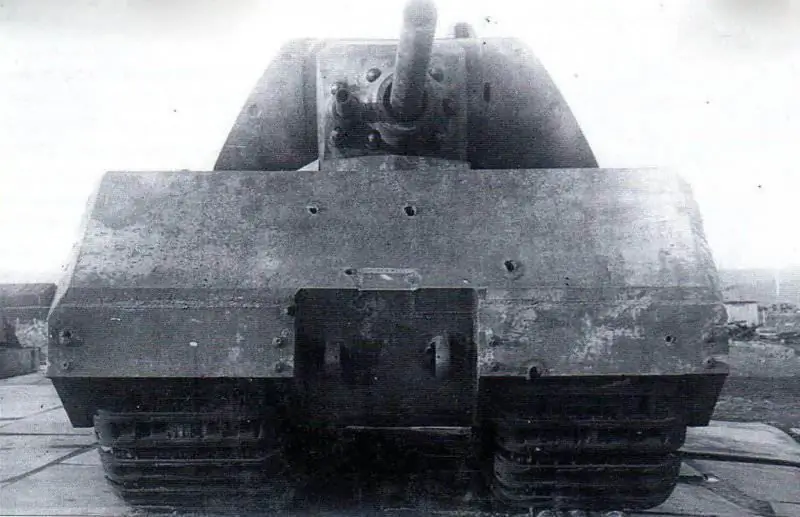
Layout
The super-heavy tank "Mouse" was a tracked combat vehicle with powerful artillery weapons. The crew consisted of six people - a tank commander, a gun commander, two loaders, a driver and a radio operator.
The body of the vehicle was divided by transverse partitions into four compartments: control, engine, combat and transmission. The control compartment was located in the bow of the hull. It housed the driver's (left) and radio operator's (right) seats, control drives, control and measuring devices, switching equipment, a radio station and fire extinguisher cylinders. In front of the radio operator's seat, in the bottom of the hull, there was a hatch for an emergency exit from the tank. In the niches of the sides, two fuel tanks with a total capacity of 1560 liters were installed. In the roof of the hull, above the driver's and radio operator's seats, there was a hatch closed by an armored cover, as well as a driver's observation device (left) and a radio operator's circular rotation periscope (right).
Directly behind the control compartment was the engine compartment, which housed the engine (in the central well), water and oil coolers of the engine cooling system (in the side niches), exhaust manifolds and an oil tank.
The fighting compartment was located behind the engine compartment in the middle of the tank hull. It housed most of the ammunition, as well as a unit for recharging batteries and powering the electric motor for turning the turret. In the central well, under the floor of the fighting compartment, a single-stage gearbox and a block of main and auxiliary generators were mounted. Rotation from the engine located in the engine compartment was transmitted to the generator through a single-stage gearbox.
A rotating turret with weapons was installed above the fighting compartment of the hull on roller supports. It contained the seats of the tank commander, the commander of the guns and loaders, a twin installation of cannons and a separately located machine gun, observation and aiming devices, turret rotation mechanisms with electromechanical and manual drives, and the rest of the ammunition. In the roof of the tower there were two manhole hatches, covered with armored covers.
Traction motors, intermediate gears, brakes and final drives were installed in the transmission compartment (in the aft part of the tank hull).
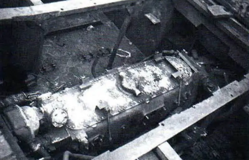
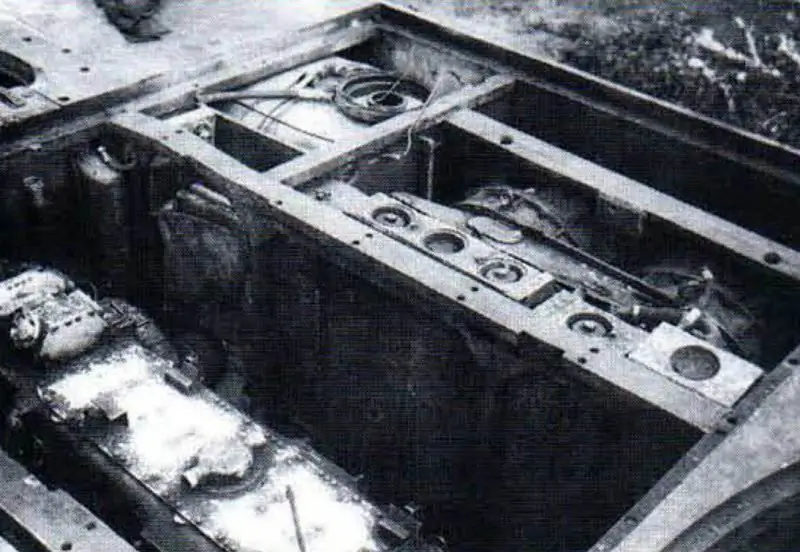
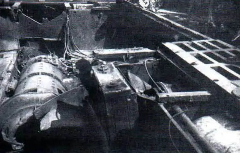
General view of the engine compartment. The installation of the carburetor engine, water radiator, oil coolers, radiator for cooling the right exhaust pipe, fans, right fuel tank and air filter is visible. In the photo on the right: the placement of generators in the fighting and engine compartments
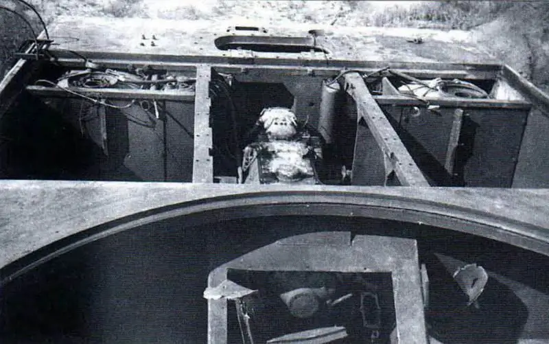
Control compartment (the driver's hatch is visible), engine compartment (right and left fuel tanks, engine); tower and a number of units are dismantled
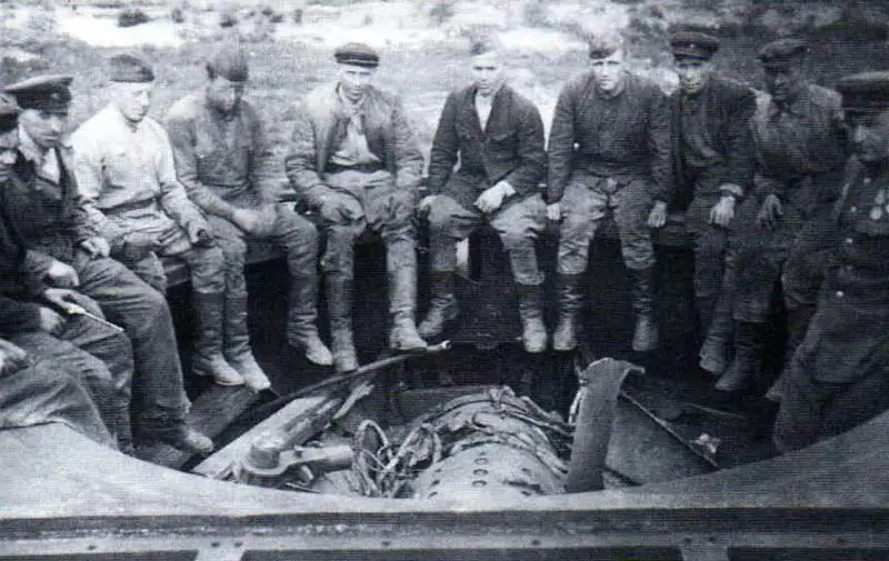
The personnel of the unit that carried out the evacuation of the tanks, on the hull Tour 205/1 with the dismantled load tower. This photo gives an idea of the size of the tower shoulder strap.
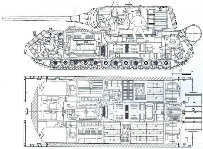
The layout of the super-heavy tank "Mouse"
Armament
The armament of the tank consisted of a 128 mm KwK.44 (PaK.44) model 1944 tank gun, a 75 mm KwK.40 tank gun paired with it, and a separate MG.42 machine gun of 7.92 mm caliber.
In the turret of the tank, the twin unit was mounted on a special machine. The armoring of the swinging part of the mask of the paired cannons is cast; the cannons were attached to the common cradle with seven bolts. Placing two tank guns in a common mask was aimed at increasing the firepower of the tank and expanding the range of targets hit. The design of the installation made it possible to use each gun separately, depending on the combat situation, but did not make it possible to conduct targeted firing in a volley.
The 128 mm KwK.44 rifled tank gun was the most powerful among German tank artillery. The length of the rifled part of the barrel of the gun was 50 calibers, the full length of the barrel was 55 calibers. The gun had a horizontal wedge breech that opened manually to the right. Recoil devices were located on top of the sides of the barrel. The shot was fired using an electric trigger.
The ammunition load of the KwK.40 gun consisted of 61 separate-case loading shots (25 shots were located in the turret, 36 in the tank hull). Two types of shells were used - armor-piercing tracer and high-explosive fragmentation.
The 75 mm KwK.40 cannon was mounted in a common mask with a 128 mm cannon to the right of it. The main differences of this gun from the existing artillery systems were the increase to 36.6 calibers of the barrel length and the lower placement of the recoil brake, due to the layout of the turret. The KwK.40 had a vertical wedge breech that opened automatically. The trigger is electromechanical. Ammunition for the gun consisted of 200 unitary shots with armor-piercing and high-explosive fragmentation shells (50 shots fit in the tower, 150 in the tank hull).
Aiming the guns at the target was carried out by the gun commander using an optical periscopic sight of the TWZF type, mounted to the left of the 128-mm cannon. The head of the sight was located in a stationary armored hood protruding above the roof of the tower. The sight was connected to the left trunnion of the 128-mm cannon using a parallelogram linkage. The vertical guidance angles ranged from -T to +23 '. An electromechanical turret rotation mechanism was used to guide the paired installation along the horizon.
The tank commander determined the distance to the target using a horizontal stereoscopic rangefinder with a base of 1.2 m, mounted in the turret roof. In addition, the commander had an observation periscope to monitor the battlefield. According to Soviet experts, despite the traditionally good qualities of German aiming and observation devices, the firepower of the super-heavy tank "Mouse" was clearly insufficient for a vehicle of this class.
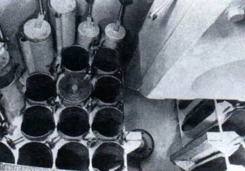
Ammunition rack for 128 mm rounds
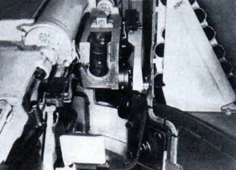
Anti-recoil devices 128 mm cannon and breech of 75 mm cannon. In the right corner of the turret, the ammo rack for 75 mm rounds is visible.
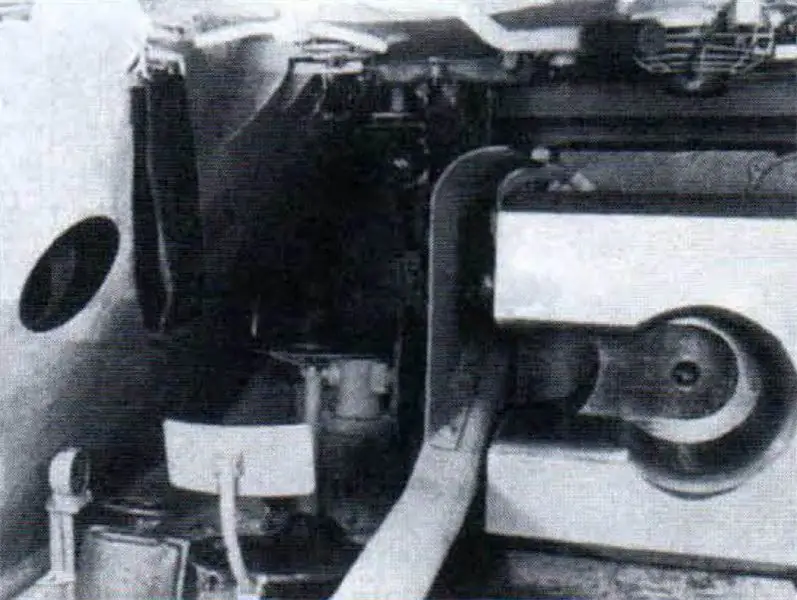
Workplace of the gun commander
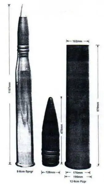
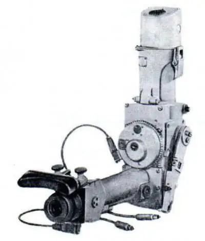
Ammunition for separate loading of 128 mm caliber. An 88 mm KwK cannon round is shown for comparison. 43 L / 71 tanks "Tiger II". Periscopic sight TWZF-1
Armor protection
The armored hull of the mouse tank was a welded structure made of rolled armor plates with a thickness of 40 to 200 mm, processed to medium hardness.
Unlike other German tanks, the Tour 205 did not have hatches or slots in the frontal and stern plates that reduced its anti-projectile resistance. The frontal and stern rolled hull plates were located with rational angles of inclination, and the side plates - vertically. The thickness of the bead sheet was not the same: the upper flange of the bead had a thickness of 185 mm, and the lower part of the bead sheet was planed at a width of 780 mm to a thickness of 105 mm. The decrease in the thickness of the lower part of the side did not entail a decrease in the level of armor protection of the components and assemblies of the tank located in the lower part of the hull, since they were additionally protected by the side armor plate of the inner well 80 mm thick. These armor plates formed a well 1000 mm wide and 600 mm deep along the tank axis, in which the control compartment, power plant, generators and other units were located.

The scheme of armor protection of the tank "Mouse" (Tour 205/2)
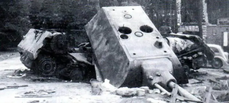
General view of the tower of the blown up tank "Mouse" (Tour 205/2)
Elements of the tank undercarriage were mounted between the outer side plate of the hull and the side plate of the inner well. Thus, the lower part of the outer side plate with a thickness of 105 mm formed the armor protection of the chassis. In front, the undercarriage was protected by armor plates in the form of visors 100 mm thick with an inclination angle of 10 °.
For the convenience of assembling components and assemblies, the hull roof was removable. It consisted of separate armor plates with a thickness of 50 mm (in the turret area) to 105 mm (above the control compartment). The thickness of the turret plate armor reached 55 mm. To protect the tower from jamming during shell fire, triangular reflective scarves of armor 60 mm thick and 250 mm high were welded on the middle sheet of the over-engine roof. In the other two sheets of the over-engine roof, there were armored air intake grilles. Unlike the first prototype, the second tank had two more armored reflectors.
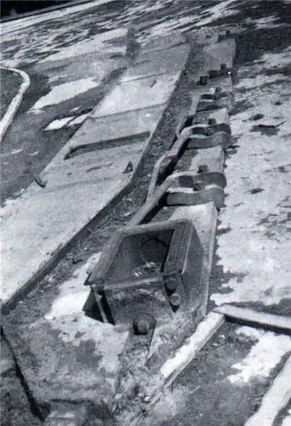
The inner side of the side of the tank hull. Its lower (planed) part is clearly visible
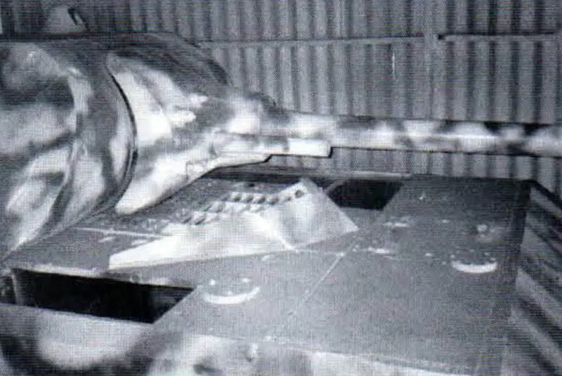
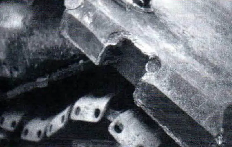
Turret plate of the tank hull with welded triangular reflective scarves. In the photo below: the frontal armor plate and its spike connection

Armored body of the tank
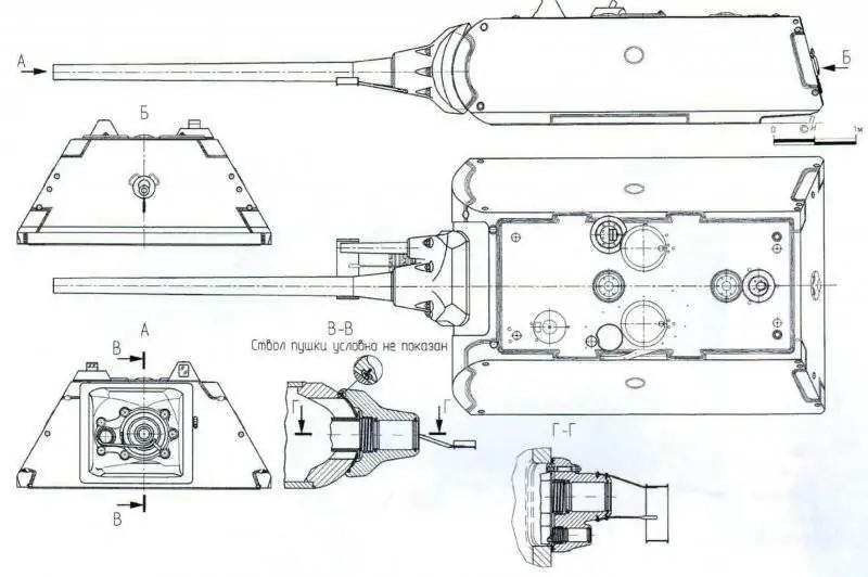
Tank tower "Mouse"
To protect against anti-tank mines, the bottom of the hull in the front part had a thickness of 105 mm, and the rest was made of 55 mm armor plate. Fenders and inner sides had armor thickness of 40 and 80 mm, respectively. This distribution of the thicknesses of the main armor parts of the hull indicated the desire of the designers to create an equal-strength shell-resistant hull. Strengthening the front of the floor and roof also significantly increased the rigidity of the hull structure as a whole. If the armored hulls of German tanks had a ratio between the thicknesses of the armor of the frontal and side parts equal to 0, 5-0, 6, then for the armored hull of the "Mouse" tank this ratio reached 0, 925, i.e. the side armor plates in their thickness approached the frontal ones.
All connections of the main body armor parts were made in a thorn. To increase the structural strength of the spike joints of the armor plates, cylindrical keys were installed at the joints of the joints, similar to the keys used in the joints of the body of the self-propelled gun "Ferdinand".
The key was a steel roller with a diameter of 50 or 80 mm, inserted into a hole drilled in the joints of the sheets to be joined after assembly for welding. The hole was made so that the drilling axis was located in the plane of the spike faces of the armor plates to be connected. If, without a key, the spike connection (before welding) was detachable, then after installing the key into the hole, the spike connection in the direction perpendicular to the axis of the key could no longer be disconnected. The use of two perpendicularly spaced keys made the connection one-piece even before the final welding. The dowels were inserted flush with the surface of the joined armor plates and welded to them along the perimeter of the base.
In addition to connecting the upper frontal plate of the hull with the lower one, the dowels were also used to connect the sides of the hull with the upper frontal, stern plates and the bottom. The connection of the stern sheets to each other was carried out in an oblique spike without a key, the rest of the connections of the armor parts of the hull (part of the roof, bottom, fenders, etc.) - in a quarter end-to-end or overlap using double-sided welding.
The turret of the tank was also welded, from rolled armor plates and cast parts from homogeneous armor of medium hardness. The frontal part was cast, cylindrical in shape, had an armor thickness of 200 mm. Side and stern sheets - flat, rolled, 210 mm thick, tower roof sheet - 65 mm thick. Thus, the tower, like the hull, was designed taking into account the equal strength of all its armor parts. The connection of the turret parts was carried out in a spike using dowels slightly different from the dowels in the hull joints.
All armor parts of the hull and turret had different hardness. Armor parts with a thickness of up to 50 mm were subjected to heat treatment for high hardness, and parts with a thickness of 160 mm were processed for medium and low hardness (HB = 3, 7-3, 8 kgf / mm2). Only the armor of the inner sides of the hull, which had a thickness of 80 mm, was heat-treated to a low hardness. Armor parts with a thickness of 185-210 mm had low hardness.
For the manufacture of armored parts of the hull and turret, six different grades of steel were used, the main of which were chromium-nickel, chromium-manganese and chromium-nickel-molybdenum steel. It should be noted that in all steel grades the carbon content was increased and was in the range of 0.3-0.45%. In addition, as in the production of armor for other tanks, there was a tendency to replace scarce alloying elements, nickel and molybdenum, with other elements - chromium, manganese and silicon. When assessing the armor protection of the Mouse tank, Soviet experts noted: “… The design of the hull does not provide for maximum use of the advantages of large design angles, and the use of vertically located side plates sharply reduces their anti-cannon resistance and makes the tank vulnerable under certain conditions when fired by domestic shells. mm guns. The large size of the hull and turret, their significant mass, negatively affect the mobility of the tank."
Power point
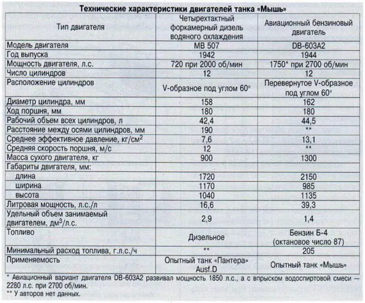
The first prototype of the Tur 205/1 tank was equipped with a twelve-cylinder V-shaped experimental pre-chamber water-cooled tank diesel from Daimler-Benz - an upgraded version of the MB 507 engine with 720 hp. (530 kW), developed in 1942 for the prototype of the Pz. Kpfw. V Ausf. D "Panther" tank. Five experimental "Panthers" were manufactured with such power plants, but these engines were not accepted into serial production.
In 1944, for use in the mouse tank, the power of the MB 507 engine was increased by pressurization to 1100-1200 hp. (812-884 kW). A tank with such a power plant was discovered in May 1945 by Soviet troops on the territory of the Stamm camp of the Kumersdorf proving ground. The vehicle was badly damaged, the engine was disassembled, and parts of it were scattered around the tank. It was possible to assemble only a few main engine components: the block head, the cylinder block jacket, the crankcase and some other elements. We could not find any technical documentation for this modification of an experienced tank diesel engine.
The second prototype of the Tur 205/2 tank was equipped with a DB-603A2 four-stroke aviation engine designed for the Focke-Wulf Ta-152C fighter and adapted by Daimler-Benz to work in the tank. The company's specialists installed a new gearbox with a drive on the cooling system fans and excluded the high-altitude fluid coupling regulator with an automatic pressure regulator, instead of which they introduced a centrifugal regulator to limit the number of maximum engine speed. Additionally, a water pump for cooling the exhaust manifolds and a plunger radial pump for the tank's servo control system were introduced. To start the engine, instead of the starter, an auxiliary electric generator was used, which was switched on to the starter mode when the engine was started.
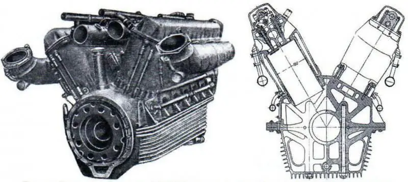
Experienced tank diesel MB 507 with a capacity of 1100-1200 hp. (812-884 kW) and its cross section
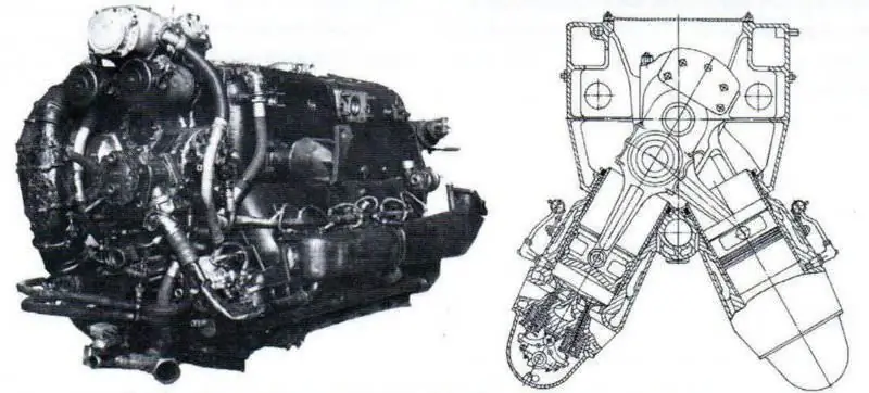
DB-603A2 carburetor engine and its cross section
The DB-603A2 (direct injection, electric ignition and supercharging) worked similarly to a carburetor engine. The difference was only in the formation of a combustible mixture in the cylinders, and not in the carburetor. The fuel was injected at a pressure of 90-100 kg / cm2 at the suction stroke.
The main advantages of this engine compared to carburetor engines were as follows:
“- due to the high filling ratio of the engine, its liter power increased by an average of 20% (the increase in engine filling was facilitated by the relatively low hydraulic resistance in the engine air paths due to the absence of carburetors, improved cleaning of the cylinders, carried out without fuel loss during purging, and an increase in weight charge by the amount of fuel injected into the cylinders);
- increased efficiency of the engine due to accurate metering of fuel in the cylinders; - lower fire hazard and the ability to operate on heavier and less scarce grades of fuel."
Compared to diesel engines, it was noted:
“- higher liter capacity due to lower values of the excess air coefficient α = 0.9-1.1 (for diesel engines α> 1, 2);
- smaller mass and volume. Reducing the specific volume of the engine was especially important for tank power plants;
- reduced dynamic tension of the cycle, which contributed to an increase in the service life of the crank-connecting rod group;
- the fuel pump of the engine with direct fuel injection and electric ignition was subject to less wear, since it worked with a lower fuel supply pressure (90-100 kg / cm2 instead of 180-200 kg / cm2) and had forced lubrication of rubbing plunger-sleeve pairs;
- comparatively easier starting of the engine: its compression ratio (6-7, 5) was 2 times lower than that of a diesel engine (14-18);
"The injector was easier to manufacture and the quality of its performance did not have much of an impact on engine performance compared to a diesel engine."
The advantages of this system, despite the absence of devices for regulating the mixture composition depending on the engine load, contributed to the intensive transfer in Germany by the end of the war of all aircraft engines to direct fuel injection. The HL 230 tank engine also introduced direct fuel injection. At the same time, the engine power with unchanged cylinder sizes was increased from 680 hp. (504 kW) up to 900 hp (667 kW). Fuel was injected into the cylinders at a pressure of 90-100 kgf / cm2 through six holes.
Fuel tanks (main) were installed in the engine compartment along the sides and occupied part of the volume of the control compartment. The total capacity of the fuel tanks was 1560 liters. An additional fuel tank was installed on the aft part of the hull, which was connected to the fuel supply system. If necessary, it could be dropped without the crew getting out of the car.
The air entering the engine cylinders was cleaned in a combined air cleaner located in the immediate vicinity of the blower inlet. The air cleaner provided preliminary dry inertial cleaning and had a dust bin. Fine air purification took place in an oil bath and in the filter elements of the air cleaner.
The engine cooling system - liquid, closed type, with forced circulation, was made separately from the cooling system of the exhaust manifolds. The capacity of the engine cooling system was 110 liters. A mixture of ethylene glycol and water in equal proportions was used as a coolant. The engine cooling system consisted of two radiators, two steam separators, a water pump, an expansion tank with a steam valve, piping, and four driven fans.
The exhaust manifold cooling system included four radiators, a water pump and a steam valve. The radiators were installed next to the radiators of the engine cooling system.
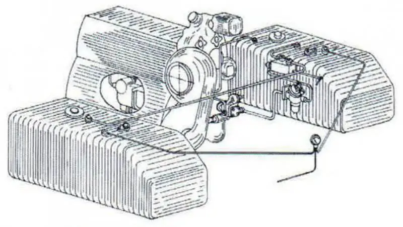
Fuel system of the engine
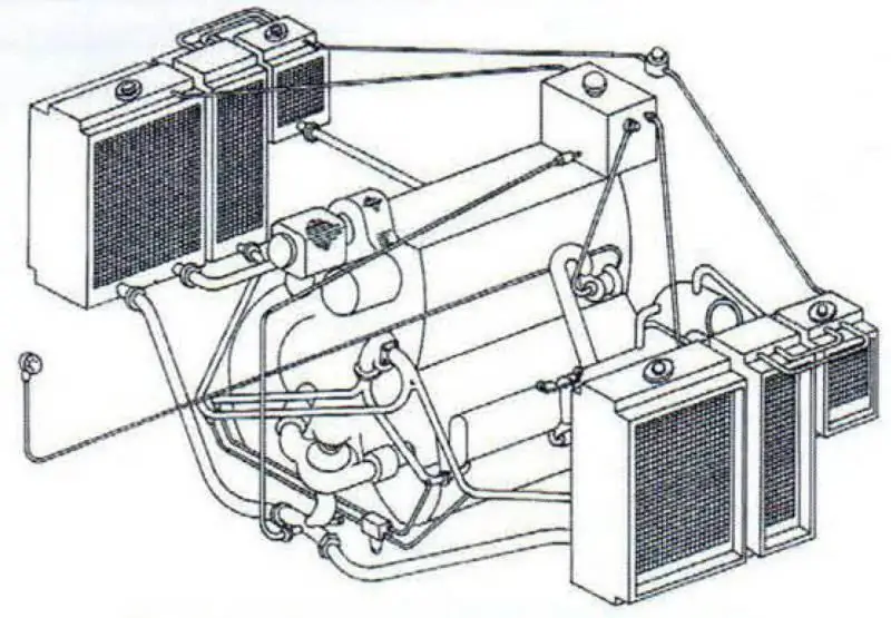
Engine cooling system
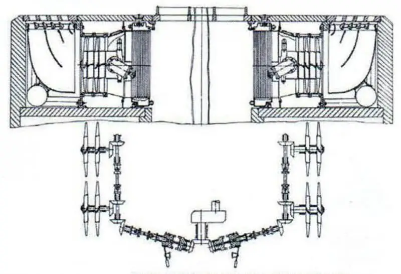
Cooling fans
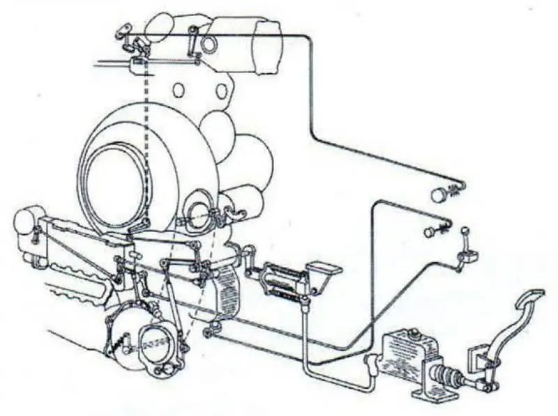
Motor control circuit
Two-stage axial fans were installed in pairs along the sides of the tank. They were equipped with guide vanes and were driven in rotation by a gear drive. The maximum fan speed was 4212 rpm. Cooling air was sucked in by fans through the armored grille of the engine compartment roof, and was thrown out through the side grilles. The cooling intensity of the engine was regulated by louvers installed under the side grilles.
Oil circulation in the engine lubrication system was ensured by the operation of ten pumps: the main injection pump, three high-pressure pumps and six evacuation pumps. Part of the oil went to lubricate the rubbing surfaces of the parts, and part to power the hydraulic clutch and servo motor control devices. A wire-slotted radiator with mechanical cleaning of the surface was used to cool the oil. The oil filter was located in the delivery line behind the pump.
The engine ignition system consisted of a Boch magneto and two glow plugs per cylinder. Ignition timing - mechanical, depending on the load. The advance mechanism had a device controlled from the driver's seat and made it possible to periodically clean the spark plugs while the engine was running.
The layout of the tank's power plant was, in fact, a further development of the layout used on the Ferdinand self-propelled guns. Good access to the engine units was ensured by their placement on the crankcase cover. The inverted position of the engine created more favorable conditions for cooling the cylinder heads and excluded the possibility of air and vapor congestion in them. However, this arrangement of the engine also had disadvantages.
So, to lower the axis of the drive shaft, it was necessary to install a special gearbox, which increased the length of the engine and complicated its design. Access to the units located in the collapse of the cylinder block was difficult. The lack of friction devices in the fan drive made it difficult to operate.
The width and height of the DB 603A-2 were within the limits of the existing designs and did not affect the overall dimensions of the tank hull. The length of the engine exceeded the length of all other tank engines, which, as noted above, was caused by the installation of a gearbox that lengthened the engine by 250 mm.
The specific volume of the DB 603A-2 engine was equal to 1.4 dm3 / hp. and was the smallest in comparison with other carburetor engines of this power. The relatively small volume occupied by the DB 603A-2 was due to the use of pressurization and direct fuel injection, which significantly increased the liter power of the engine. High-temperature liquid cooling of exhaust manifolds, isolated from the main system, made it possible to increase the reliability of the engine and make its operation less fire hazardous. As you know, the air cooling of the exhaust manifolds used on the Maybach HL 210 and HL 230 engines turned out to be ineffective. Overheating of exhaust manifolds often led to fires in tanks.
Transmission
One of the most interesting features of the super-heavy tank "Mouse" was the electromechanical transmission, which made it possible to significantly facilitate machine control and increase the durability of the engine due to the absence of a rigid kinematic connection with the drive wheels.
The electromechanical transmission consisted of two independent systems, each of which included a generator and a traction motor powered by it and consisted of the following main elements:
- a block of main generators with an auxiliary generator and a fan;
- two traction electric motors;
- generator-exciter;
- two controllers-rheostats;
- switching unit and other control equipment;
- rechargeable batteries.
The two main generators, which supplied the traction motors with current, were located in a special generator room behind the piston engine. They were installed on a single base and, thanks to the direct rigid connection of the armature shafts, formed a generator unit. In the block with the main generators there was a third auxiliary generator, the armature of which was mounted on the same shaft as the rear generator.
An independent excitation winding, in which the current strength could be changed by the driver in the range from zero to the maximum value, made it possible to change the voltage taken from the generator from zero to nominal and, therefore, to regulate the rotation speed of the traction motor and the speed of the tank movement.
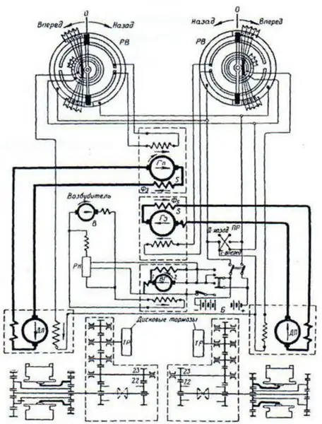
Electromechanical transmission diagram
An auxiliary DC generator, with the piston engine running, fed the independent excitation windings of both main generators and traction motors, and also charged the battery. At the time of starting the piston engine, it was used as a conventional electric starter. In this case, it was powered by electric energy from a storage battery. The independent excitation winding of the auxiliary generator was powered by a special exciter generator driven by a piston engine.
The scheme of air cooling of electric transmission machines, implemented in the tank Tour 205, was of interest. The air taken by the fan from the drive side entered through the rectifier into the generator shaft and, flowing around the body from the outside, reached the grate located between the bodies of the front and rear main generators. Here the air flow was divided: part of the air moved further along the shaft into the aft compartment, where, diverging to the right and left, it entered the traction motors and, cooling them, was thrown into the atmosphere through the openings in the roof of the aft hull. Another part of the air flow entered through the grating inside the generators' casings, blew the frontal parts of the anchors of both generators and, dividing, was directed along the ventilation ducts of the anchors to the collectors and brushes. From there, the air flow entered the air collecting pipes and through them was discharged into the atmosphere through the middle openings in the roof of the aft hull.
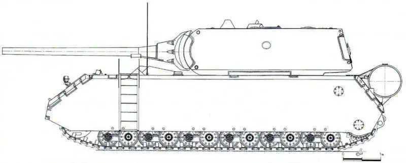
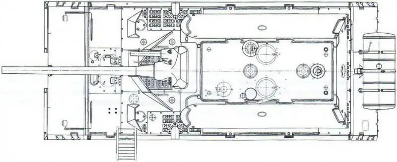
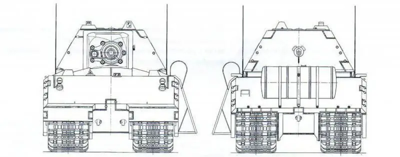
General view of the super-heavy tank "Mouse"
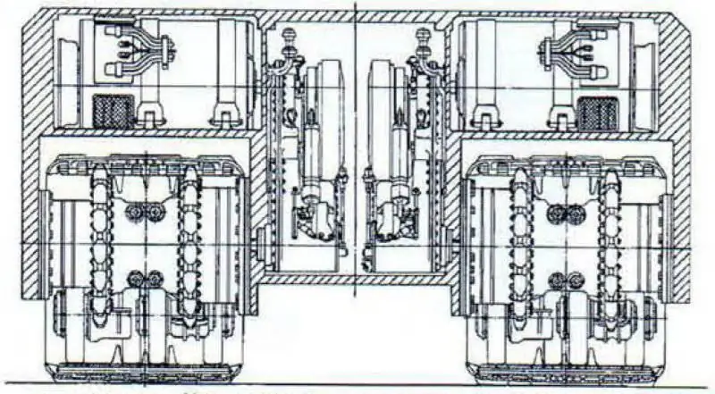
Cross section of the tank in the transmission compartment
DC traction motors with independent excitation were located in the aft compartment, one engine per track. The torque of the shaft of each electric motor was transmitted through a two-stage intermediate gearbox to the drive shaft of the final drive and then to the drive wheels. The independent motor winding was powered by an auxiliary generator.
The control of the rotation speed of the traction motors of both tracks was carried out according to the Leonardo scheme, which gave the following advantages:
- wide and smooth regulation of the speed of rotation of the electric motor was carried out without losses in the starting rheostats;
-easy control of starting and braking was ensured by reversing the electric motor.
The generator-exciter of the type LK1000 / 12 R26 of the "Bosch" company was located on the prime mover and fed the independent excitation winding of the auxiliary generator. It worked in a unit with a special relay-regulator, which ensured a constant voltage at the terminals of the auxiliary generator in the speed range from 600 to 2600 rpm at a maximum current supplied to the network, 70 A. traction electric motors on the rotation speed of the auxiliary generator armature, and therefore on the rotation speed of the crankshaft of the internal combustion engine.
For the electromechanical transmission of the tank, the following operating modes were characteristic: starting the engine, moving in a straight line forward and backward, turns, braking and special cases of using an electromechanical transmission.
The internal combustion engine was started electrically using an auxiliary generator as a starter, which was then transferred to the generator mode.
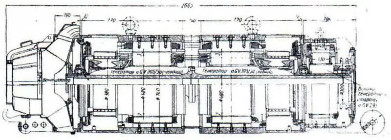
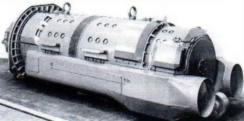
Longitudinal section and general view of the generating unit
For a smooth start of the movement of the tank, the handles of both controllers were simultaneously moved by the driver from the neutral position forward. The increase in speed was achieved by increasing the voltage of the main generators, for which the handles were moved further from the neutral position forward. In this case, the traction motors developed power proportional to their speed.
If it was necessary to turn the tank with a large radius, the traction engine in the direction of which they were going to turn was turned off.
To reduce the turning radius, the electric motor of the lagging track was slowed down, putting it in the generator mode. The electricity received from it was realized by reducing the excitation current of the corresponding main generator, turning it on in the electric motor mode. In this case, the torque of the traction motor was opposite in direction, and a normal force was applied to the track. At the same time, the generator, operating in the electric motor mode, facilitated the operation of the piston engine, and the tank could be turned with an incomplete take-off of power from the piston engine.
To turn the tank around its axis, both traction motors were commanded to rotate in the opposite direction. In this case, the handles of one controller were moved from neutral in the forward position, the other in the backward position. The farther from neutral the controller knobs were, the steeper the turn was.
The braking of the tank was carried out by transferring the traction motors to the generator mode and using the main generators as electric motors that rotate the engine crankshaft. To do this, it was enough to reduce the voltage of the main generators, making it less than the voltage generated by the electric motors, and to release the gas with the piston engine fuel supply pedal. However, this braking power delivered by the electric motors was relatively small and more efficient braking required the use of hydraulically controlled mechanical brakes mounted on intermediate gears.
The scheme of the electromechanical transmission of the mouse tank made it possible to use the electric power of the tank's generators not only to power its own electric motors, but also to power the electric motors of another tank (for example, when driving underwater). In this case, the transmission of electricity was supposed to be carried out using a connecting cable. The movement control of the tank that received the energy was carried out from the tank that supplied it, and was limited by changing the speed of movement.
The significant power of the internal combustion engine of the "Mouse" tank made it difficult to repeat the scheme used on the ACS "Ferdinand" (that is, with the automatic use of the power of the piston engine in the entire range of speeds and thrust forces). And although this scheme was not automatic, with a certain qualification of the driver, the tank could be driven with a fairly full use of the power of the piston engine.
The use of an intermediate gearbox between the electric motor shaft and the final drive facilitated the operation of the electrical equipment and made it possible to reduce its weight and dimensions. It should also be noted the successful design of electric transmission machines and especially their ventilation system.
The electromechanical transmission of the tank, in addition to the electrical part, had two mechanical units on each side - an intermediate gearbox with an onboard brake and a final gearbox. They were connected to the power circuit in series behind the traction motors. In addition, a single-stage gearbox with a gear ratio of 1.05 was installed in the engine crankcase, introduced for layout reasons.
To expand the range of gear ratios implemented in the electromechanical transmission, the intermediate gear, installed between the electric motor and the final drive, was made in the form of a guitar, which consisted of cylindrical gears and had two gears. The gear shift control was hydraulic.
The final drives were located inside the housings of the drive wheels. The main elements of the transmission have been constructively worked out and carefully finished. The designers paid special attention to increasing the reliability of the units, facilitating the working conditions of the main parts. In addition, it was possible to achieve a significant compactness of the units.
At the same time, the design of individual transmission units was traditional and did not represent technical novelty. However, it should be noted that the improvement of assemblies and parts allowed German specialists to increase the reliability of such units as the guitar and the brake, while simultaneously creating more stressful operating conditions for the final drive.
Chassis
All units of the undercarriage of the tank were located between the main side plates of the hull and the bulwarks. The latter were the armor protection of the chassis and the second support for attaching the units of the tracked propeller and suspension, Each track of the tank consisted of 56 solid and 56 composite tracks, alternating with each other. The one-piece track was a shaped casting with a smooth inner treadmill on which there was a guide ridge. There were seven symmetrically located eyelets on each side of the track. The integral track consisted of three cast parts, with the two end parts being interchangeable.
The use of compound tracks, alternating with solid tracks, provided (in addition to reducing the mass of the tracks) less wear of rubbing surfaces due to an increase in the number of hinges.
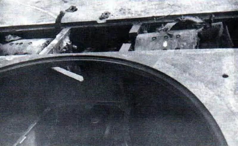
Transmission department. The bore of the roof of the tank hull under the turret ring is clearly visible
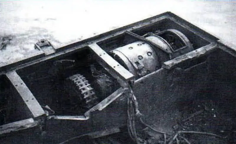
Left side electric motor. In the middle part of the body there is an intermediate gearbox of the left side with a brake
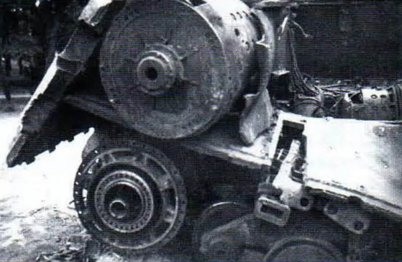
Installing the drive wheel and starboard final drive. Above is the starboard electric motor
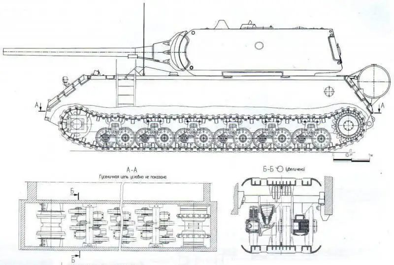
Undercarriage of the tank "Mouse"
The connection of the tracks was carried out with fingers, which were kept from axial displacement by spring rings. The tracks, cast from manganese steel, were heat treated - hardened and tempered. The track pin was made of rolled medium carbon steel with subsequent surface hardening with high frequency currents. The weight of the integral and composite track with the pin was 127.7 kg, the total weight of the tank tracks was 14302 kg.
The gearing with the driving wheels is pinned. The drive wheels were mounted between two stages of the planetary final drive. The drive wheel housing consisted of two halves connected by four bolts. This design greatly facilitated the installation of the drive wheel. Removable gear rims were bolted to the flanges of the drive wheel housing. Each crown had 17 teeth. The drive wheel housing was sealed with two labyrinth felt seals.
The idler body was a hollow shaped casting made in one piece with two rims. At the ends of the axis of the guide wheel, planes were cut off and through radial drills were made with a semicircular thread, into which the screws of the tensioning mechanism were screwed. When the screws rotated, the planes of the axles moved in the guides of the side plate of the hull and bulwark, due to which the caterpillar was tensioned.
It should be noted that the absence of a crank mechanism has greatly simplified the design of the idler. At the same time, the weight of the idler wheel assembly with the track tensioning mechanism was 1750 kg, which complicated the assembly and disassembly work during their replacement or repair.
The suspension of the tank hull was carried out using 24 bogies of the same design, placed in two rows along its sides.
The bogies of both rows were attached in pairs to one (common to them) cast bracket, which was fixed on one side to the side plate of the hull, and on the other to the bulwark.
The two-row arrangement of the bogies was due to the desire to increase the number of road wheels and thereby reduce the load on them. The elastic elements of each carriage were a rectangular conical buffer spring and a rubber cushion.
The schematic diagram and design of individual units of the undercarriage were also partially borrowed from the Ferdinand self-propelled guns. As already mentioned, in Germany, when designing the Tour 205, they were forced to abandon the torsion bar suspension used on all other types of heavy tanks. Documents indicate that at the factories, when assembling tanks, they experienced significant difficulties with torsion bar suspensions, since their use required a large number of holes in the tank hull. These difficulties were especially aggravated after the Allied bomber aircraft disabled a special plant for processing tank hulls. In this regard, since 1943, the Germans have been designing and testing other types of suspensions, in particular, suspensions with buffer springs and leaf springs. Despite the fact that when testing the suspension of the "Mouse" tank, lower results were obtained than the torsion suspensions of other heavy tanks, buffer springs were still used as elastic elements.
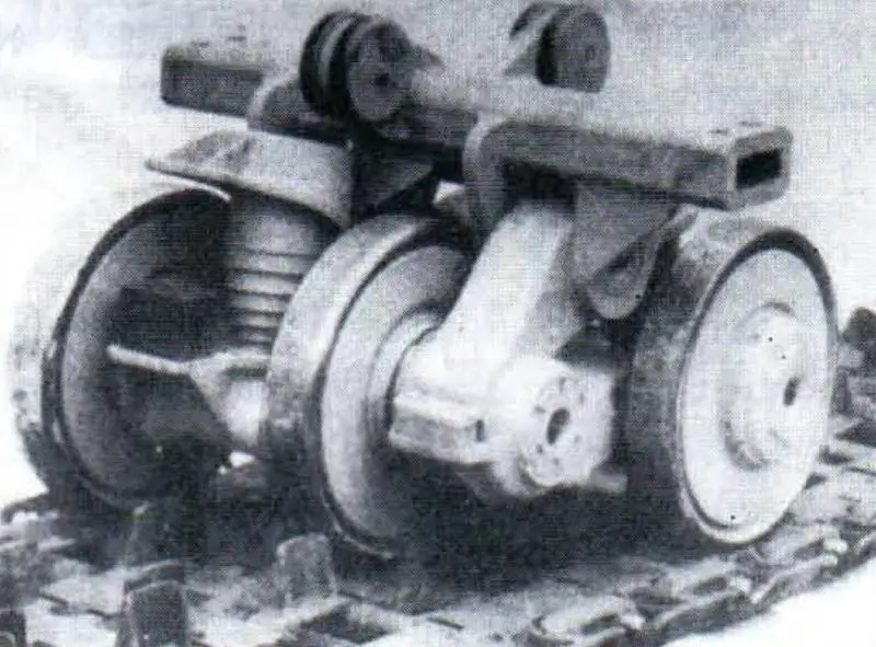
Support bogie undercarriage of the tank
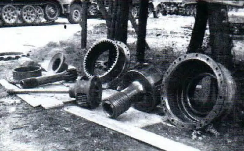
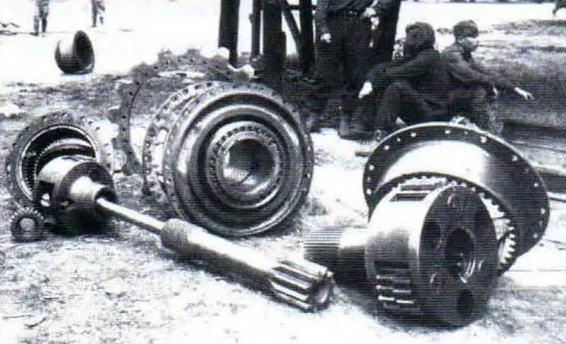
Details of the planetary gearbox. In the photo on the right: the planetary gear parts are stacked in the order they are installed on the tank: left (first) planetary gearbox, drive wheel, right (second) planetary gearbox
Each bogie had two road wheels connected by a lower balancer. The design of the road wheels was the same. Fastening the track roller to the hub with a key and nut, in addition to the simplicity of the design, ensured ease of assembly and disassembly. Internal shock absorption of the road roller was provided by two rubber rings sandwiched between a cast T-section rim and two steel discs. The weight of each roller was 110 kg.
When hitting an obstacle, the rim of the roller moved upward, causing deformation of the rubber rings and thereby damping vibrations going to the body. The rubber in this case worked for shear. The use of internal cushioning of road wheels for a 180-ton slow-moving machine was a rational solution, since external tires did not provide their reliable operation under conditions of high specific pressures. The use of small-diameter rollers made it possible to install a large number of bogies, but this entailed overstressing the rubber rings of the road wheels. However, the internal cushioning of the road wheels (with their small diameter) provided less stress in the rubber compared to the outside tires and significant savings in scarce rubber.
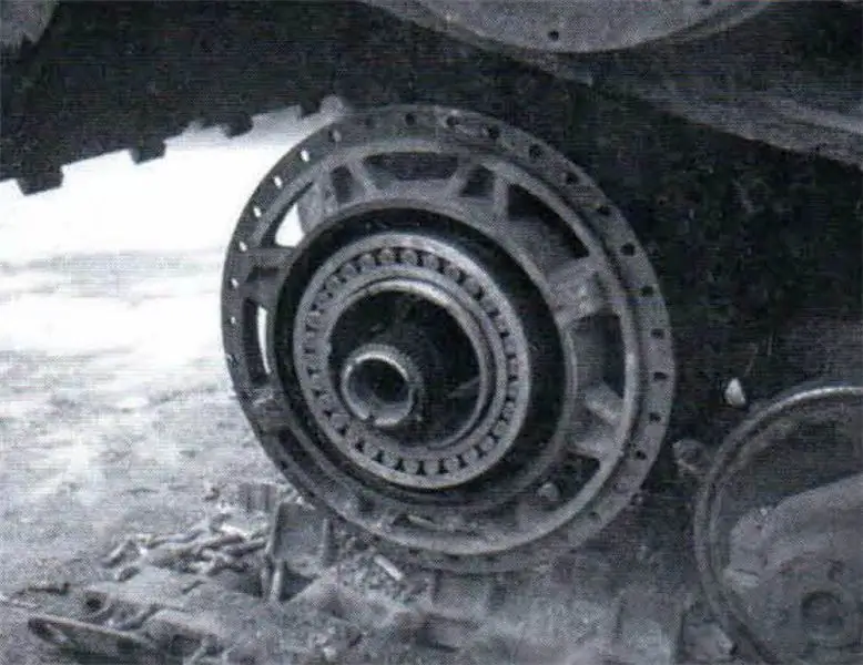
Installing the drive wheel. The crown is removed
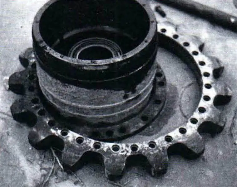
Removable drive wheel rim
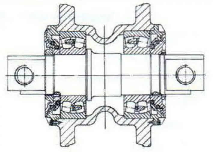
Idler wheel design

Drive wheel design
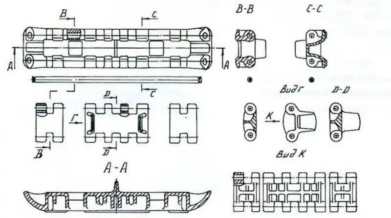
One-piece and composite track design
It should be noted that the attachment of the rubber pad to the balancer with two rubber-vulcanized bolts proved to be unreliable. Most of the rubber pads were lost after a short test. Assessing the design of the undercarriage, Soviet experts made the following conclusions:
“- the placement of the undercarriage assemblies between the bulwark and the side plate of the hull made it possible to have two supports for the caterpillar propeller and suspension assemblies, which ensured greater strength of the entire undercarriage;
- the use of a single non-separable bulwark made it difficult to access the undercarriage units and complicated assembly and disassembly work;
- the two-row arrangement of the suspension bogies made it possible to increase the number of road wheels and reduce the load on them;
- the use of a suspension with buffer springs was a forced decision, since with equal volumes of elastic elements, spiral buffer springs had less efficiency and provided worse driving performance compared to torsion bar suspensions."
Underwater driving equipment
The significant mass of the "Mouse" tank created serious difficulties in overcoming water obstacles, given the low probability of the presence of bridges capable of withstanding this vehicle (and even more so their safety in war conditions). Therefore, the possibility of underwater driving was initially incorporated into its design: it was provided to overcome water obstacles up to 8 m deep along the bottom with a duration of stay under water up to 45 minutes.
To ensure the tightness of the tank when moving at a depth of 10 m, all openings, dampers, joints and hatches had gaskets capable of withstanding water pressure up to 1 kgf / cmg. The tightness of the joint between the swinging mask of the twin guns and the turret was achieved by additional tightening of the seven armor mounting bolts and a rubber gasket installed along the perimeter of its inner side. When the bolts were unscrewed, the armor of the mask was returned to its original position by means of two cylindrical springs on the cannon barrels between the cradles and the mask.
The tightness of the joint between the hull and the turret of the tank was ensured by the original design of the turret support. Instead of the traditional ball bearing, two bogie systems were used. Three vertical carts served to support the tower on a horizontal treadmill, and six horizontal ones - to center the tower in a horizontal plane. When overcoming the water obstacle, the tank tower with the help of worm drives that raised the vertical carts, lowered onto the shoulder strap and, due to its large mass, tightly pressed the rubber gasket installed along the perimeter of the shoulder strap, which achieved sufficient tightness of the joint.
Combat and technical characteristics of the tank "Mouse"
Total information
Combat weight, t ………………………………………… 188
Crew, people ……………………………………………….6
Specific power, hp / t …………………………..9, 6
Average ground pressure, kgf / cm2 ……………… 1, 6
Main dimensions, mm Length with gun:
forward ………………………………………………… 10200
back ………………………………………………….. 12500
Height …………………………………………………… 3710
Width …………………………………………………. 3630
Support surface length ……………………… 5860
Ground clearance on the main bottom ……………………..500
Armament
Cannon, brand ……………. KWK-44 (PaK-44); KWK-40
caliber, mm ………………………………………… 128; 75
ammunition, rounds ……………………………..68; 100
Machine guns, quantity, brand ……………….1xMG.42
caliber, mm …………………………………………….7, 92
Ammunition, cartridges ……………………………..1000
Armor protection, mm / tilt angle, degrees
Body forehead ……………………………… 200/52; 200/35
Hull board ………………………………… 185/0; 105/0
Feed ……………………………………… 160/38: 160/30
Roof …………………………………………… 105; 55; 50
Bottom ………………………………………………… 105; 55
Tower forehead ……………………………………………….210
Tower board ………………………………………….210 / 30
Tower roof ……………………………………………..65
Mobility
Maximum speed on the highway, km / h ………….20
Cruising on the highway, km …………………………….186
Power point
Engine, brand, type ……………………… DB-603 A2, aviation, carburetor
Maximum power, hp ……………………. 1750
Means of communication
Radio station, brand, type ……..10WSC / UKWE, VHF
Communication range
(telephone / telegraph), km …………… 2-3 / 3-4
Special equipment
PPO system, type ………………………………… Manual
number of cylinders (fire extinguishers) …………………..2
Equipment for underwater driving ……………………………….. OPVT set
The depth of the water obstacle to be overcome, m ………………………………………………… 8
Duration of the crew stay under water, min ………………………….. Up to 45
The metal air supply pipe, intended to ensure the operation of the power plant under water, was mounted on the driver's hatch and secured with steel braces. An additional pipe, enabling the evacuation of the crew, was located on the turret. The composite structure of the air supply pipes made it possible to overcome water obstacles of various depths. Waste exhaust gases were discharged into the water through the check valves installed on the exhaust pipes.
To overcome a deep ford, it was possible to transmit electrical energy through a cable to a tank moving under water from a tank on the shore.
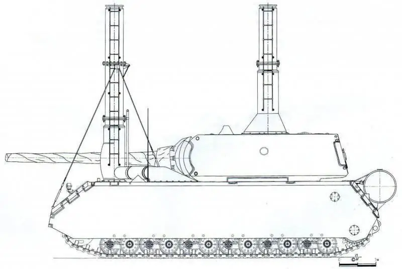
Underwater tank driving equipment
General assessment of the tank design by domestic specialists
According to domestic tank builders, a number of fundamental shortcomings (the main one being insufficient firepower with significant dimensions and weight) did not allow relying on any effective use of the Tour 205 tank on the battlefield. Nevertheless, this vehicle was of interest as the first practical experience of creating a super-heavy tank with maximum allowable levels of armor protection and firepower. In its design, the Germans applied interesting technical solutions, which were even recommended for use in domestic tank building.
Of undoubted interest was the constructive solution for connecting armor parts of large thickness and dimensions, as well as the execution of individual units to ensure the reliability of the systems and the tank as a whole, the compactness of the units in order to reduce weight and dimensions.
It was noted that the compactness of the engine and transmission cooling system was achieved through the use of high-pressure two-stage fans and high-temperature liquid cooling of the exhaust manifolds, which increased the reliability of the engine.
The systems that serviced the engine used a quality control system of the working mixture, taking into account barometric pressure and temperature conditions, a steam separator and an air separator of the fuel system.
In the transmission of the tank, the design of electric motors and electric generators was recognized as deserving of attention. The use of an intermediate gearbox between the traction motor shaft and the final drive made it possible to reduce the tension in the operation of electrical machines, to reduce their weight and dimensions. German designers paid special attention to ensuring the reliability of transmission units while ensuring their compactness.
In general, the constructive ideology implemented in the German super-heavy tank "Mouse", taking into account the combat experience of the Great Patriotic War, was assessed as unacceptable and leading to a dead end.
The fighting at the final stage of the war was characterized by deep raids of tank formations, their forced transfers (up to 300 km) caused by tactical necessity, as well as fierce street battles with the massive use of anti-tank cumulative melee weapons (faust patrons). Under these conditions, Soviet heavy tanks, acting in conjunction with medium T-34s (without limiting the latter in terms of movement speed), moved forward and successfully solved the entire range of tasks assigned to them when breaking through the defense.
Based on this, as the main directions for the further development of domestic heavy tanks, priority was given to strengthening armor protection (within reasonable values of the tank's combat mass), improving observation and fire control devices, increasing the power and rate of fire of the main weapon. To combat enemy aircraft, it was required to develop a remotely controlled anti-aircraft gun for a heavy tank, providing fire on ground targets.
These and many other technical solutions were envisaged for implementation in the design of the first post-war experimental heavy tank "Object 260" (IS-7).


