- Author Matthew Elmers elmers@military-review.com.
- Public 2023-12-16 21:49.
- Last modified 2025-06-01 06:23.
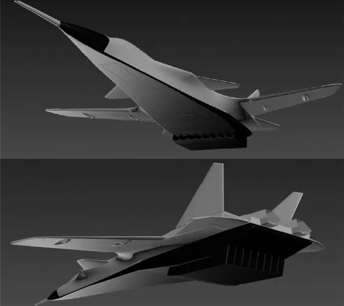
At present, OAO NPO Molniya is developing a multi-mode hypersonic unmanned aerial vehicle on the subject of research and development work "Hammer". This UAV is considered as a prototype demonstrator of the technologies of a hypersonic unmanned accelerator aircraft with a combined screen turbo-ramjet power plant. The key technology of the prototype is the use of a ramjet engine (ramjet) with a subsonic combustion chamber and a screen air intake device.
Calculated and experimental parameters of the demonstrator prototype:
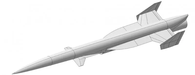
The background of this R&D was a project of a multi-mode supersonic unmanned aerial vehicle (MSBLA) developed by JSC NPO Molniya, in which the aerodynamic appearance of a promising unmanned or manned accelerator aircraft was determined. The key technology of MSBLA is the use of a ramjet engine (ramjet) with a subsonic combustion chamber and a screen air intake device. Design parameters of MSBLA: cruising Mach numbers M = 1.8 … 4, flight altitudes from low to H ≈ 20,000 m, launch weight up to 1000 kg.
The air inlet layout studied at the SVS-2 stand of TsAGI showed low efficiency of the ventral wedge shield used, made "at the same time" with the fuselage (Fig. A) and a rectangular shield with a span equal to the fuselage width (Fig. B).

Both of them ensured the approximate constancy of the recovery coefficients of the total pressure ν and the flow rate f in the angle of attack, instead of increasing them.
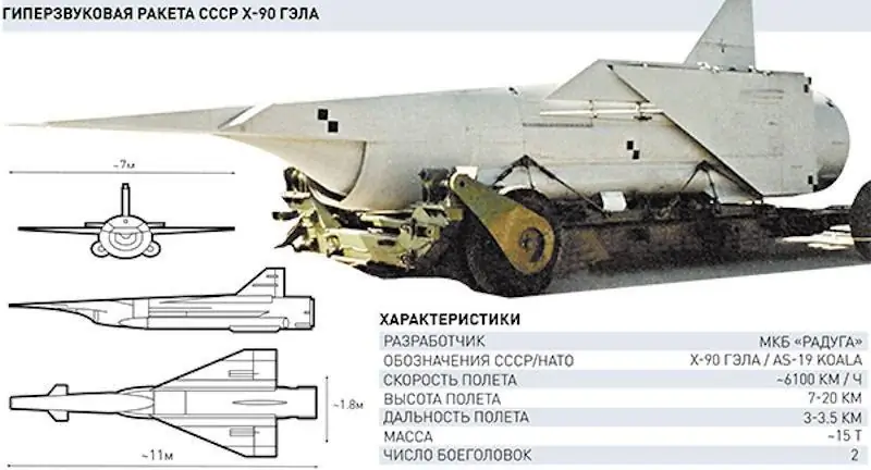
Since the frontal screen of the type used on the Kh-90 rocket was not suitable for the MSBLA, as a prototype of an accelerator aircraft, it was decided, on the basis of experimental studies of TsAGI in the early 80s, to develop a ventral screen, retaining the configuration with a two-stage central body obtained by test results.
In the course of two stages of experimental research on a special stand SVS-2 TsAGI, December 2008 - February 2009 and March 2010, with an intermediate stage of numerical search studies, a screen air intake device (EHU) with a two-stage conical body having different calculated numbers was developed. Mach in steps, which made it possible to obtain acceptable thrust in a wide range of Mach numbers.
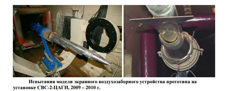
The effect of the screen consists in an increase in the flow rate and recovery coefficients with an increase in the angle of attack at Mach numbers M> 2.5. The magnitude of the positive gradient of both characteristics increases with increasing Mach number.

EVZU was first developed and applied on the X-90 hypersonic experimental aircraft developed by NPO Raduga (cruise missile, according to NATO classification AS-19 Koala)
As a result, an aerodynamic configuration of the prototype was developed according to the "hybrid" scheme named by the authors with the integration of the EHU into the carrier system.
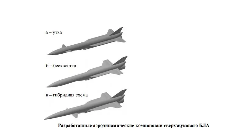
The hybrid scheme has features of both a "duck" scheme (by the number and location of bearing surfaces) and a "tailless" scheme (by the type of longitudinal controls). A typical MSBLA trajectory includes a launch from a ground-based launcher, acceleration with a solid-propellant booster to a supersonic ramjet launch speed, flight according to a given program with a horizontal segment and braking to a low subsonic speed with a soft parachute landing.
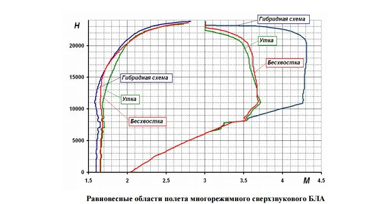
It can be seen that the hybrid layout, due to a greater ground effect and optimization of the aerodynamic layout for a minimum of drag at α = 1.2 ° … 1.4 °, implements significantly higher maximum flight Mach numbers M ≈ 4.3 in a wide range of altitudes H = 11 … 21 km. The "duck" and "tailless" schemes reach the maximum value of the number М = 3.72 … 3.74 at the height Н = 11 km. In this case, the hybrid scheme has a small gain due to the shift in the minimum resistance and at low Mach numbers, having a range of flight numbers M = 1.6 … 4.25 at an altitude of H ≈ 11 km. The smallest area of equilibrium flight is realized in the "duck" scheme.
The table shows the calculated flight performance data for the developed layouts for typical flight paths.
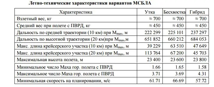
The flight ranges, which have the same level for all versions of the MSBLA, have shown the possibility of successfully creating an accelerator aircraft with a slightly increased relative reserve of kerosene fuel with supersonic flight ranges of the order of 1500-2000 km for return to the home airfield. At the same time, the developed hybrid layout, which is a consequence of the deep integration of the aerodynamic scheme and the screen air intake of the ramjet engine, had a clear advantage in terms of maximum flight speeds and the range of altitudes in which the maximum speeds are realized. The absolute values of the Mach number and flight altitude, reaching Мmax = 4.3 at Нmax Mmax = 20,500 m, make it possible to speak of the feasibility of a reusable aerospace system with a hypersonic high-altitude booster aircraft at the level of existing technologies in Russia. a single-use space stage is 6-8 times as compared to a launch from the ground.
This aerodynamic layout was the final option for considering a reusable multi-mode unmanned aerial vehicle of high supersonic flight speeds.
Concept and general layout
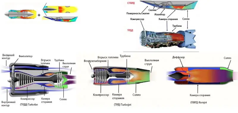
A distinctive requirement for an overclocking aircraft, in comparison with its small-sized prototype, is take-off / landing on an aircraft from existing airfields and the need to fly at Mach numbers less than the Mach number of launching a ramjet engine M <1.8 … 2. This determines the type and composition of the combined power plant of the aircraft - a ramjet engine and turbojet engines with an afterburner (TRDF).
On the basis of this, the technical appearance and general layout of the accelerator aircraft for the light class transport space system was formed with a design carrying capacity of about 1000 kg into a low-earth orbit of 200 km. An assessment of the weight parameters of a liquid two-stage orbital stage based on an oxygen-kerosene engine RD-0124 was carried out by the method of characteristic velocity with integral losses, based on the conditions of launch from the accelerator.
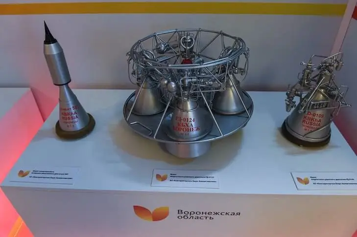
At the first stage, the RD-0124 engine (void thrust 30,000 kg, specific impulse 359 s) is installed, but with a reduced frame diameter and close chambers, or the RD-0124M engine (differs from the base one by one chamber and a new nozzle of a larger diameter); at the second stage, an engine with one chamber from RD-0124 (a void thrust of 7,500 kg is assumed). Based on the received weight report of the orbital stage with a total weight of 18,508 kg, its configuration was developed, and on its basis - the layout of a hypersonic booster aircraft with a take-off weight of 74,000 kg with a combined power plant (KSU).
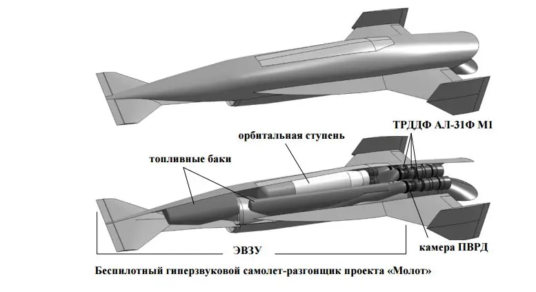
KSU includes:
TRDF and ramjet engines are located in a vertical package, which allows each of them to be mounted and serviced separately. The entire length of the vehicle was used to accommodate a ramjet engine with an EVC of the maximum size and, accordingly, thrust. The maximum take-off weight of the vehicle is 74 tons. The empty weight is 31 tons.
The section shows an orbital stage - a two-stage liquid launch vehicle weighing 18, 5 tons, injecting a 1000 kg launch vehicle into a low-earth orbit of 200 km. Also visible are 3 TRDDF AL-31FM1.
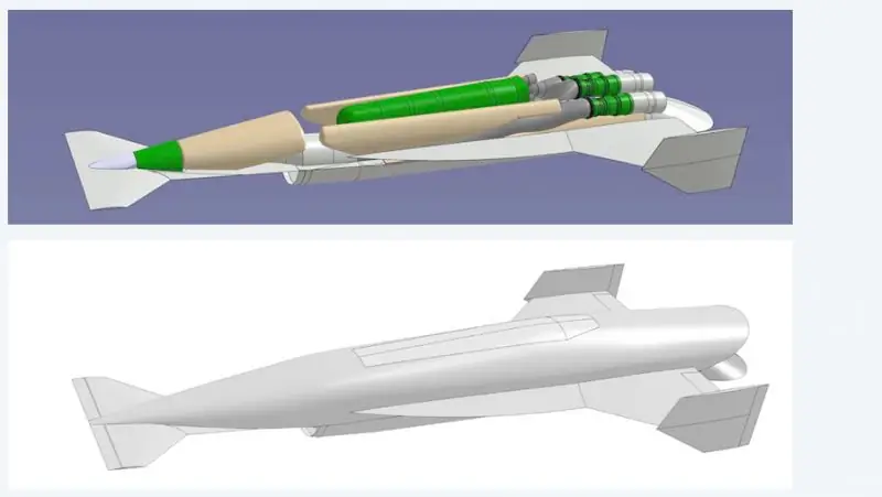
Experimental testing of a ramjet engine of this size is supposed to be carried out directly in flight tests, using a turbojet engine for acceleration. When developing a unified air intake system, the basic principles were adopted:
Implemented by separating the air ducts for the turbojet engine and the ramjet engine behind the supersonic part of the air intake and the development of a simple transformer device that converts the supersonic part of the EHU into unregulated configurations "round trip", while simultaneously switching the air supply between the channels. The EVZU of the vehicle on takeoff operates on a turbojet engine, when the speed is set to M = 2, 0, it switches to the ramjet engine.
The payload compartment and the main fuel tanks are located behind the transformer EVCU in a horizontal package. The use of storage tanks is necessary for thermal decoupling of the "hot" fuselage structure and "cold" heat-insulated tanks with kerosene. The TRDF compartment is located behind the payload compartment, which has flow channels for cooling the engine nozzles, the design of the compartment and the upper flap of the ramjet nozzle when the TRDF is operating.
The principle of operation of the EVZU transformer of the booster aircraft excludes, with an accuracy of a small value, the force resistance on the moving part of the device from the side of the incoming flow. This allows you to minimize the relative mass of the air intake system by reducing the weight of the device itself and its drive compared to traditional adjustable rectangular air intakes. The ramjet engine has a splitting nozzle-drainer, which in a closed form during the operation of the turbojet engine provides an uninterrupted flow of the flow around the fuselage. When opening the drain nozzle at the transition to the ramjet engine operating mode, the upper flap closes the bottom section of the turbojet engine compartment. The open ramjet nozzle is a supersonic confuser and, with a certain degree of underexpansion of the ramjet jet, which is realized at high Mach numbers, provides an increase in thrust due to the longitudinal projection of the pressure forces on the upper flap.
Compared to the prototype, the relative area of the wing consoles has been significantly increased due to the need for aircraft takeoff / landing. Wing mechanization includes only elevons. The keels are equipped with rudders that can be used as brake flaps when landing. To ensure uninterrupted flow at subsonic flight speeds, the screen has a deflectable nose. The landing gear of the accelerator aircraft is four-pillar, with placement along the sides to exclude the ingress of dirt and foreign objects into the air intake. This scheme has been tested on the EPOS product - an analogue of the orbital aircraft system "Spiral", which allows, similarly to a bicycle chassis, to "squat" on takeoff.

A simplified solid model in the CAD environment was developed to determine the flight weights, the position of the center of mass and the self-moments of inertia of the booster aircraft.
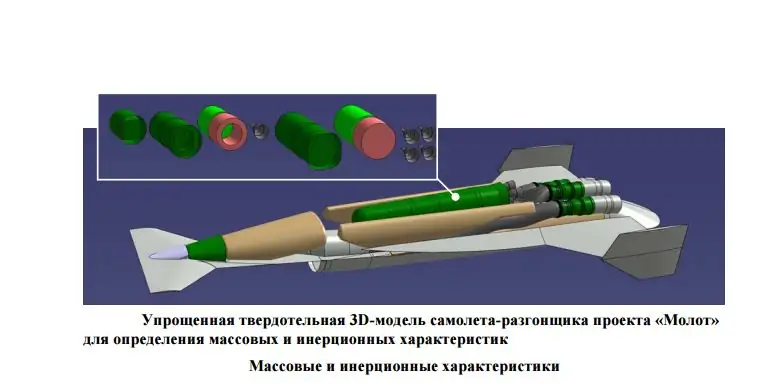
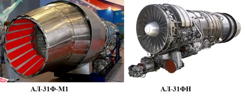
The structure, power plant and equipment of the booster aircraft were divided into 28 elements, each of which was evaluated according to a statistical parameter (specific weight of the reduced skin, etc.) and was modeled by a geometrically similar solid element. For the construction of the fuselage and bearing surfaces, weighted statistics for MiG-25 / MiG-31 aircraft were used. The mass of the AL-31F M1 engine is taken "after the fact". Different percentages of kerosene filling were modeled by truncated solid-state "casts" of the internal cavities of the fuel tanks.
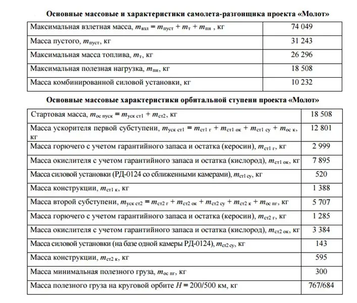
A simplified solid-state model of the orbital stage was also developed. The masses of the structural elements were taken on the basis of data on the I block (the third stage of the Soyuz-2 launch vehicle and the promising Angara launch vehicle) with the allocation of constant and variable components depending on the mass fuel.
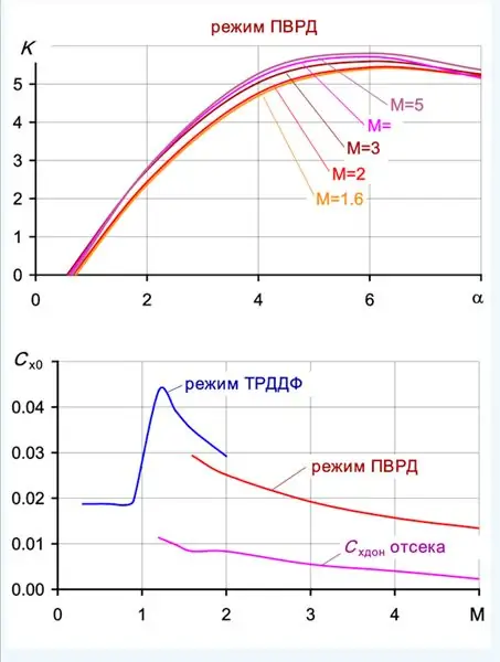
Some features of the obtained results of aerodynamics of the developed aircraft:
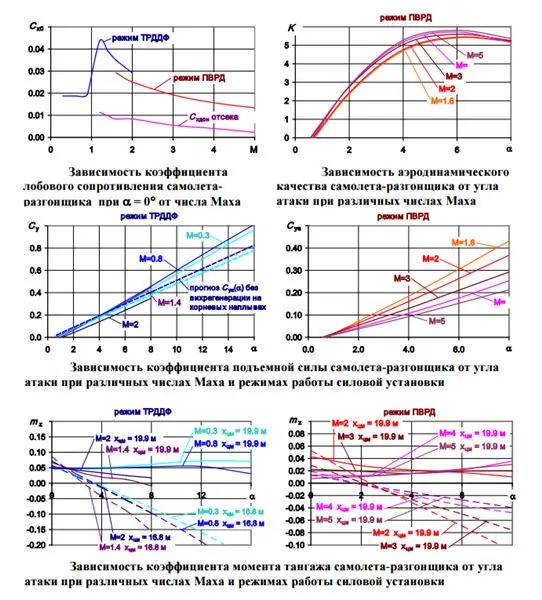
On the accelerator aircraft, to increase the flight range, the gliding mode is used when configuring for a ramjet, but without supplying fuel to it. In this mode, a drain nozzle is used, which reduces its solution when the ramjet engine is turned off to the area of the flow that provides the flow in the EHU channel, such that the thrust of the subsonic diffuser of the channel becomes equal to the resistance of the nozzle:
Pdif EVCU = Xcc ramjet. Simply put, the principle of operation of the throttling device is used on the SVS-2 TsAGI type air-to-air test installations. The podsobranny nozzle-drain opens the bottom section of the TRDF compartment, which begins to create its own bottom resistance, but less than the resistance of the switched off ramjet with supersonic flow in the air intake channel. In tests of the EVCU on the SVS-2 TsAGI installation, stable operation of the air intake with Mach number M = 1.3 was shown, therefore, it can be argued that the planning mode with the use of a drain nozzle as an EVCU throttle in the range 1.3 ≤ M ≤ Mmax can be asserted.
Flight performance and typical flight path
The task of the booster aircraft is to launch an orbital stage from the side in flight, at an altitude, flight speed and trajectory angle that meet the condition of the maximum payload mass in the reference orbit. At the preliminary stage of research on the Hammer project, the task is to achieve the maximum altitude and flight speed of this aircraft when using the “slide” maneuver to create large positive values of the trajectory angle on its ascending branch. In this case, the condition is set to minimize the velocity head when separating the stage for a corresponding decrease in the mass of the fairing and to reduce the loads on the payload compartment in the open position.
The initial data on the operation of the engines were the flight traction and economic characteristics of the AL-31F, corrected according to the bench data of the AL-31F M1 engine, as well as the characteristics of the prototype ramjet engine recalculated in proportion to the combustion chamber and the screen angle.
In fig. shows the areas of horizontal steady flight of a hypersonic accelerator aircraft in various modes of operation of the combined power plant.
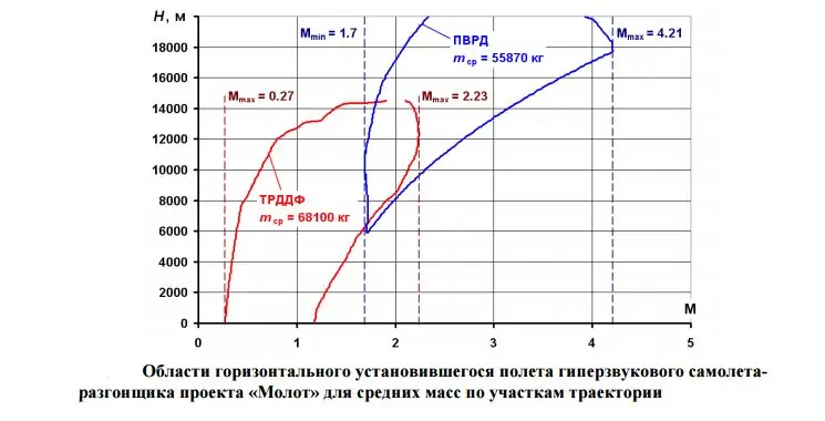
Each zone is calculated for the average over the corresponding section of the accelerator of the "Hammer" project for the average masses along the sections of the flight mass trajectory of the vehicle. It can be seen that the booster plane reaches the maximum flight Mach number M = 4.21; when flying on turbojet engines, the Mach number is limited to M = 2.23. It is important to note that the graph illustrates the need to provide the required ramjet thrust for the accelerator aircraft in a wide range of Mach numbers, which was achieved and determined experimentally during the work on the prototype screen air intake device. Takeoff is carried out at a lift-off speed V = 360 m / s - the bearing properties of the wing and screen are sufficient without the use of takeoff and landing mechanization and hovering of elevons. After the optimal climb on the horizontal section H = 10,700 m, the booster aircraft reaches supersonic sound from the subsonic Mach number M = 0.9, the combined power plant switches at M = 2 and preliminary acceleration to Vopt at M = 2.46. In the process of climbing on a ramjet, the booster plane makes a turn to the home airfield and reaches an altitude of H0pik = 20,000 m with a Mach number M = 3.73.
At this altitude, a dynamic maneuver begins to reach the maximum flight altitude and trajectory angle for launching the orbital stage. A gently sloping dive is performed with acceleration to M = 3.9 followed by a "slide" maneuver. The ramjet engine ends its work at an altitude of H ≈ 25000 m and the subsequent climb occurs due to the kinetic energy of the booster. The launch of the orbital stage takes place on the ascending branch of the trajectory at an altitude of Нpusk = 44,049 m with a Mach number М = 2.05 and a trajectory angle θ = 45 °. The booster plane reaches the height Hmax = 55,871 m on the "hill". On the descending branch of the trajectory, upon reaching the Mach number M = 1.3, the ramjet engine → turbojet engine is switched to eliminate the surge of the ramjet air intake.
In the configuration of the turbojet engine, the booster plane plans before entering the glide path, having a fuel supply on board Ggzt = 1000 kg.
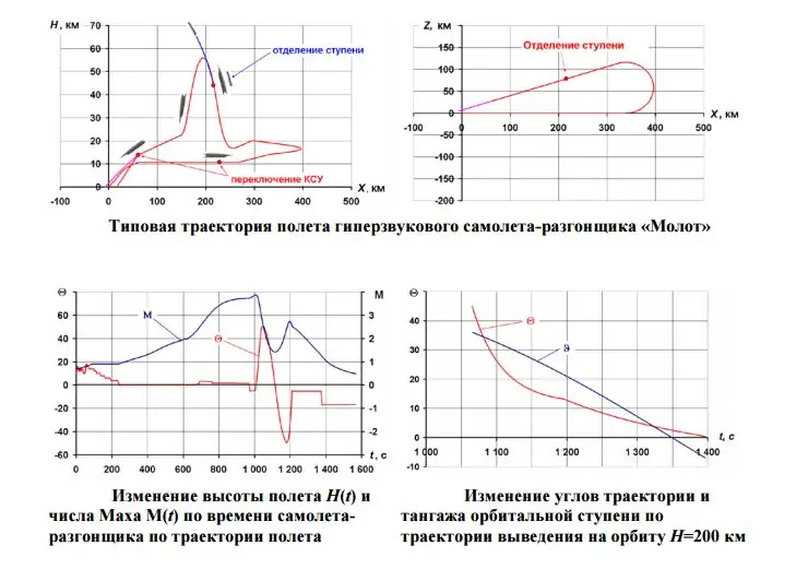
In the normal mode, the entire flight from the moment the ramjet is turned off to landing occurs without the use of engines with a margin for gliding range.
The change in the angular parameters of the step movement is shown in this figure.
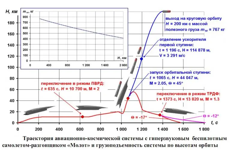
When injected into a circular orbit H = 200 km at an altitude of H = 114 878 m at a speed of V = 3 291 m / s, the accelerator of the first sub-stage is separated. The mass of the second sub-stage with a load in orbit H = 200 km is 1504 kg, of which the payload is mpg = 767 kg.
The scheme of application and flight path of the Hammer project hypersonic accelerator aircraft has an analogy with the American "university" project RASCAL, which is being created with the support of the government department DARPA.

A feature of the Molot and RASCAL projects is the use of a dynamic maneuver of the "slide" type with passive access to high launch altitudes of the orbital stage Нpusk ≈ 50,000 m at low high-speed heads; for the Molot, q launch = 24 kg / m2. The altitude of the launch makes it possible to reduce the gravitational losses and the flight time of an expensive disposable orbital stage, that is, its total mass. Small high-speed launch heads make it possible to minimize the mass of the payload fairing or even refuse it in some cases, which is essential for systems of the ultralight class (mпгН200 <1000 kg).
The principal advantage of the Hammer project booster aircraft over RASCAL is the absence of onboard liquid oxygen supplies, which simplifies and reduces the cost of its operation and excludes the untapped technology of aviation reusable cryogenic tanks. The thrust-to-weight ratio in the ramjet engine operation mode allows the Molot booster to reach on the ascending branch of the "slide" of the "workers" for the orbital stage of the trajectory angles θ launch ≈ 45 °, while the RASCAL accelerator provides its orbital stage with the starting trajectory angle only θ launch ≈ 20 ° with subsequent losses due to the step turnover maneuver.
In terms of specific carrying capacity, the aerospace system with the Molot hypersonic unmanned accelerator is superior to the RASCAL system: (mпгН500 / mvzl) hammer = 0.93%, (mпнН486 / mvzl) rascal = 0.25%
Thus, the technology of a ramjet engine with a subsonic combustion chamber (the "key" of the Hammer project), developed and mastered by the domestic aerospace industry, surpasses the promising American technology MIPCC for injecting oxygen into the TRDF air intake tract in hypersonic booster aircraft.
A hypersonic unmanned accelerator aircraft weighing 74,000 kg performs takeoff from an airfield, acceleration, climb along an optimized trajectory with an intermediate turn to the takeoff point to an altitude of H = 20,000 m and M = 3.73, a dynamic "slide" maneuver with an intermediate acceleration in a canopy diving up to M = 3.9. On the ascending branch of the trajectory at H = 44,047 m, M = 2, a two-stage orbital stage with a mass of 18,508 kg, designed on the basis of the RD-0124 engine, is separated.
After passing the "slide" Hmax = 55 871 m in the gliding mode, the booster flies to the airfield, with a guaranteed fuel supply of 1000 kg and a landing weight of 36 579 kg. The orbital stage injects into a circular orbit H = 200 km a payload with mass mpg = 767 kg, at H = 500 km mpg = 686 kg.
Reference.
1. The laboratory testing base of NPO "Molniya" includes the following laboratory complexes:
2. A this is a HEXAFLY-INT high-speed civil aircraft project
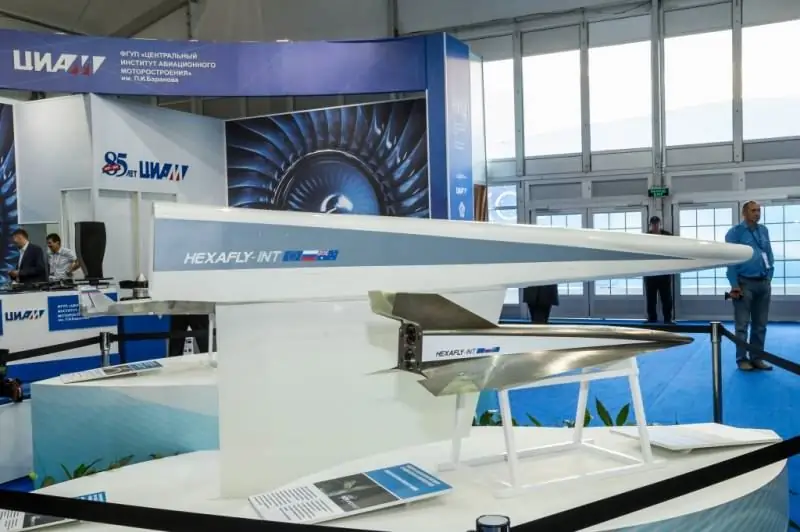
Which is one of the largest international cooperation projects. It involves leading European (ESA, ONERA, DLR, CIRA, etc.), Russian (TsAGI, CIAM, LII, MIPT) and Australian (The University of Sydney, etc.) organizations.
3. Rostec did not allow the bankruptcy of the company that developed the space shuttle "Buran"
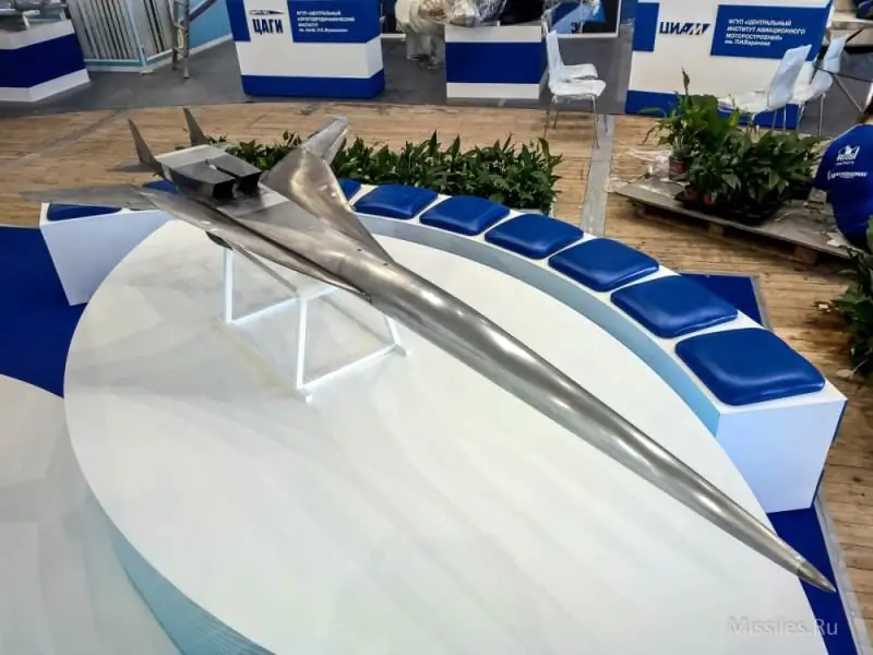
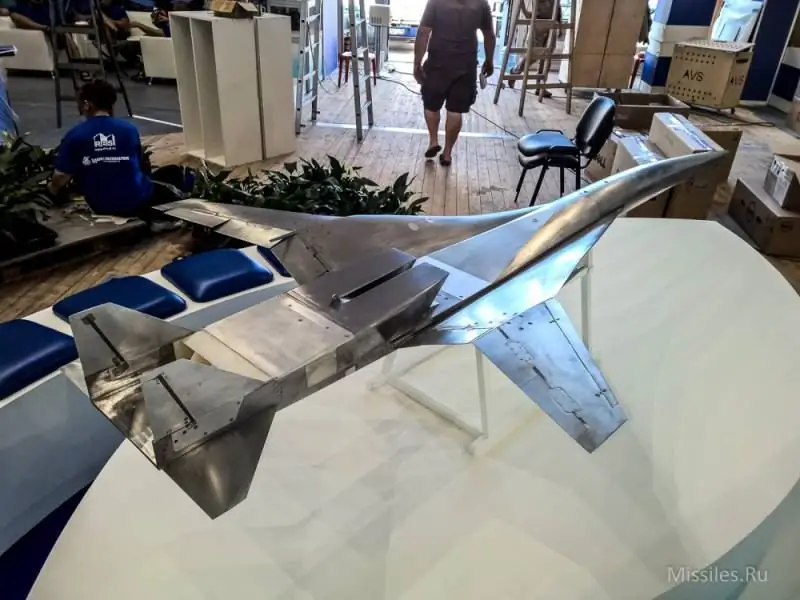
Note: The 3-D model at the beginning of the article has nothing to do with the research and development "Hammer".


