- Author Matthew Elmers elmers@military-review.com.
- Public 2023-12-16 21:49.
- Last modified 2025-06-01 06:23.
The interference effect on the guidance systems of guided weapons first appeared in the equipment of tanks in the 80s and received the name of the complex of optical-electronic countermeasures (KOEP). At the forefront were the Israeli ARPAM, the Soviet "Shtora" and the Polish (!) "Bobravka". The technique of the first generation recorded a single laser pulse as a sign of ranging, but the series of pulses was perceived as the work of a target designator for guiding a semi-active homing head of an attacking missile. Silicon photodiodes with a spectral range of 0.6-1.1 µm were used as sensors, and the selection was tuned to select pulses shorter than 200 µs. Such equipment was relatively simple and cheap, therefore it was widely used in world tank technology. The most advanced models, the RL1 from TRT and the R111 from Marconi, had an additional night channel for recording continuous infrared radiation from enemy active night vision devices. Over time, such a high-tech was abandoned - there were many false positives, and the appearance of passive night vision and thermal imagers also affected. Engineers tried to make all-angle detection systems for laser illumination - Fotona proposed a single LIRD device with a receiving sector of 3600 in azimuth.
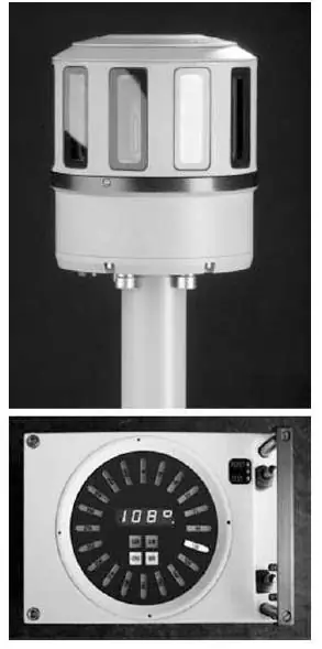
FOTONA LIRD-4 device. Source: "News of the Russian Academy of Missile and Artillery Sciences"
A similar technique was developed at the offices of Marconi and Goodrich Corporation under the designations, respectively, Type 453 and AN / VVR-3. This scheme did not take root due to the inevitable hit of the protruding parts of the tank in the receiving sector of the equipment, which led either to the appearance of "blind" zones, or to beam re-reflection and signal distortion. Therefore, the sensors were simply placed along the perimeter of the armored vehicles, thereby providing an all-round view. Such a scheme was implemented in a series by the English HELIO with a set of LWD-2 sensor heads, the Israelis with LWS-2 in the ARPAM system, Soviet engineers with TSHU-1-11 and TSHU-1-1 in the famous "Shtora" and the Swedes from Saab Electronic Defense Systems with LWS300 sensors in active protection LEDS-100.
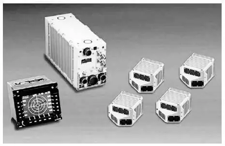
LWS-300 equipment set of the LEDS-100 complex. Source: "News of the Russian Academy of Missile and Artillery Sciences"
The common features of the indicated technique are the receiving sector of each of the heads in the range from 450 up to 900 in azimuth and 30…600 by the corner of the place. This configuration of the view is explained by the tactical methods of using anti-tank guided weapons. A strike can be expected either from ground targets or from flying equipment, which is wary of air defense covering tanks. Therefore, attack aircraft and helicopters usually illuminate tanks from low altitudes in sector 0 … 200 in elevation with the subsequent launch of the rocket. The designers took into account the possible fluctuations of the armored vehicle body and the field of view of the sensors in elevation became slightly larger than the angle of air attack. Why not put a sensor with a wide viewing angle? The fact is that the lasers of the proximity fuses of artillery shells and mines work on the top of the tank, which, by and large, are too late and useless to jam. The Sun is also a problem, the radiation of which is capable of illuminating the receiving device with all the ensuing consequences. Modern rangefinders and target designators, for the most part, use lasers with wavelengths of 1, 06 and 1, 54 microns - it is for such parameters that the sensitivity of the receiving heads of registration systems is sharpened.
The next step in the development of the equipment was the expansion of its functionality to the ability to determine not only the fact of irradiation, but also the direction to the source of laser radiation. The first generation systems could only roughly indicate enemy illumination - all due to the limited number of sensors with a wide azimuth field of view. For more accurate positioning of the enemy, it would be necessary to weigh the tank with several dozen photodetectors. Therefore, matrix sensors appeared on the scene, such as the FD-246 photodiode of the TShU-1-11 device of the Shtora-1 system. The photosensitive field of this photodetector is divided into 12 sectors in the form of stripes, onto which the laser radiation transmitted through the cylindrical lens is projected. To put it simply, the sector of the photodetector, which recorded the most intense laser illumination, will determine the direction to the radiation source. A little later, a germanium laser sensor FD-246AM appeared, designed to detect a laser with a spectral range of 1.6 microns. This technique allows you to achieve a sufficiently high resolution of 2 … 30 within the sector viewed by the receiving head up to 900… There is another way to determine the direction to the laser source. For this, signals from several sensors are jointly processed, the entrance pupils of which are located at an angle. The angular coordinate is found from the ratio of the signals from these laser receivers.
The requirements for the resolution of the equipment for recording laser radiation depend on the purpose of the complexes. If it is necessary to accurately aim a power laser emitter to create interference (Chinese JD-3 on the Object 99 tank and the American Stingray complex), then permission is required on the order of one or two arc minutes. Less strict to resolution (up to 3 … 40) are suitable in systems when it is necessary to turn the weapon in the direction of the laser illumination - this is implemented in the KOEP "Shtora", "Varta", LEDS-100. And already a very low resolution is permissible for setting smoke screens in front of the sector of the proposed rocket launch - up to 200 (Polish Bobravka and English Cerberus). At the moment, the registration of laser radiation has become a mandatory requirement for all COECs used on tanks, but guided weapons have switched to a qualitatively different guidance principle, which posed new questions for engineers.
The system of teleorientation of missiles by laser beams has become a very common "bonus" of anti-tank guided weapons. It was developed in the USSR in the 60s and implemented on a number of anti-tank systems: Bastion, Sheksna, Svir, Reflex and Kornet, as well as in the camp of a potential enemy - MAPATS from Rafael, Trigat concern MBDA, LNGWE from Denel Dynamics, as well as Stugna, ALTA from the Ukrainian "Artem". The laser beam in this case issues a command signal to the rocket tail, more precisely, to the on-board photodetector. And he does it extremely cleverly - the coded laser beam is a continuous sequence of pulses with frequencies in the kilohertz range. Do you feel what this is about? Each laser pulse hitting the receiving window of the COEC is below their threshold response level. That is, all the systems turned out to be blind in front of the command-beam ammunition guidance system. Fuel was added to the fire with the pancratic emitter system, according to which the width of the laser beam corresponds to the plane of the rocket's photodetector, and as the ammunition is removed, the angle of divergence of the beam generally decreases! That is, in modern ATGMs, the laser may not hit the tank at all - it will focus exclusively on the tail of the flying rocket. This, of course, became a challenge - at present, intensive work is underway to create a receiving head with increased sensitivity, capable of detecting a complex command-beam laser signal.
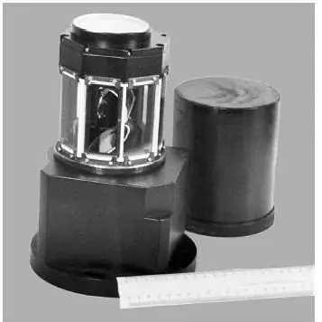
A prototype of the equipment for recording the radiation of command-beam guidance systems. Source: "News of the Russian Academy of Missile and Artillery Sciences"
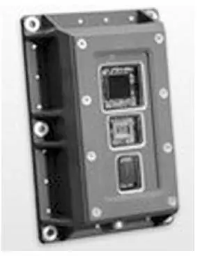
Receiving head of the AN / VVR3. Source: "News of the Russian Academy of Missile and Artillery Sciences"
This should be the BRILLIANT laser jamming station (Beamrider Laser Localization Imaging and Neutralization Tracker), developed in Canada by the DRDS Valcartier Institute, as well as the developments of Marconi and BAE Systema Avionics. But there are already serial samples - the universal indicators 300Mg and AN / VVR3 are equipped with a separate channel for determining the command-beam systems. True, this is so far only the assurances of the developers.
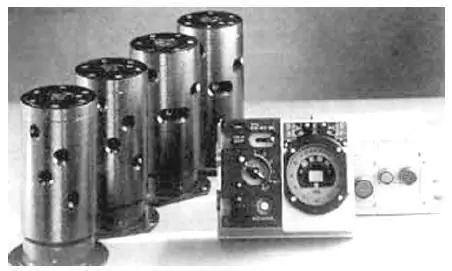
SSC-1 Obra radiation registration equipment set. Source: "News of the Russian Academy of Missile and Artillery Sciences"
The real danger is the modernization program of the Abrams SEP and SEP2 tanks, according to which the armored vehicles are equipped with a GPS thermal imaging sight, in which the rangefinder has a carbon dioxide laser with an "infrared" wavelength of 10.6 microns. That is, at the moment, absolutely most of the tanks in the world will not be able to recognize irradiation by the rangefinder of this tank, since they are "sharpened" for the laser wavelength of 1, 06 and 1, 54 microns. And in the USA they have already modernized more than 2 thousand of their Abrams in this way. Soon target designators will also switch to carbon dioxide laser! Unexpectedly, the Poles distinguished themselves by installing on their PT-91 receiving head SSC-1 Obra from the PCO company, capable of distinguishing laser radiation in the range of 0.6 … 11 microns. Everyone else will now again have to return to their armor infrared photodetectors (as Marconi and Goodrich Corporation previously did) based on ternary compounds of cadmium, mercury and tellurium, capable of detecting infrared lasers. For this, systems for their electrical cooling will be built, and in the future, possibly, all infrared channels of the KOEP will be transferred to uncooled microbolometers. And all this while maintaining all-round visibility, as well as traditional channels for lasers with wavelengths of 1, 06 and 1, 54 microns. In any case, engineers from the defense industry will not sit idly by.


