- Author Matthew Elmers [email protected].
- Public 2023-12-16 21:49.
- Last modified 2025-01-24 09:17.
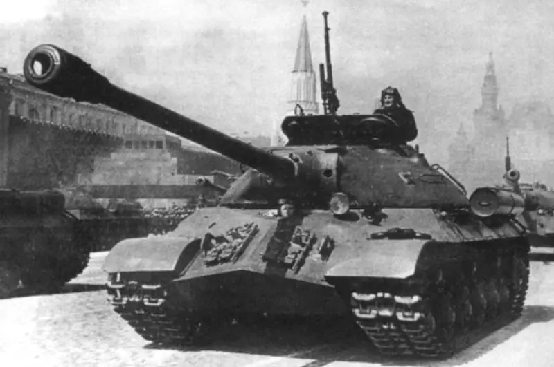
Heavy tanks IS-3 on Red Square. May 1, 1949
After the end of World War II, the armored and mechanized troops of the Red Army (since 1953 - the Soviet Army) were armed with heavy tanks IS-1, IS-2 and IS-3 5, as well as a small number of previously released KB-1C and KV-85'78.
Serial production of the IS-3 tanks continued in 1945-1946. at ChKZ (the only plant for the production of heavy tanks in the country at that time) and was discontinued in connection with the start of production of the IC-4 tank. In total, 1,430 IS-3 tanks were assembled in the post-war period.
In the course of serial production, various improvements were made to the design of the IS-3 tank, and a number of R&D projects were carried out to improve its combat and technical characteristics. So, for example, in 1945-1946. to increase the rate of fire of the tank, work was carried out on the use of unitary 122-mm rounds in the ammunition load with the placement of their packing in the fighting compartment. In addition, along with an assessment of the possibility of using more powerful artillery weapons in the IS-3 than the D-25T, the issues of automating the loading of the gun, the electric drive of the turret rotation with the command control system (target designation) and improving the ventilation of the fighting compartment, as well as visibility from the tank were considered. A project was developed to install a coaxial heavy machine gun (12, 7-mm DShK) in the turret instead of a 7, 62-mm DTM machine gun.
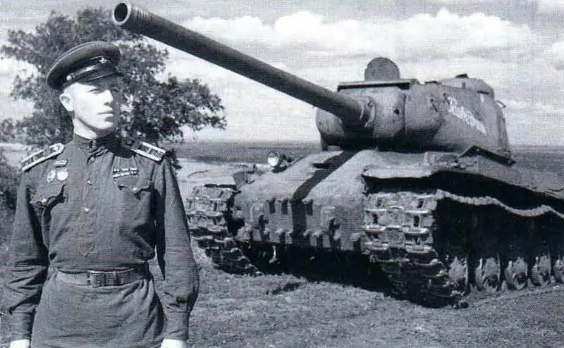
Tank IS-2, muzzle brake removed. Post-war years. Combat weight -46 tons; crew - 4 people; weapons: cannon - 122 mm, 3 machine guns - 7, 62 mm, 1 machine gun - 12, 7 mm; anti-cannon armor protection; engine power - 382 kW (520 hp); the maximum speed is 37 km / h.
However, the work on the placement of unitary 122-mm shots and the test laying of their mock-ups showed the impossibility of placing these shots and the lack of ease of use due to the limited internal volumes of the turret. With regard to the introduction of a coaxial heavy machine gun DShK, then its installation required alteration of the turret, movable armor, as well as a change in the packing of shells and charges (casings). Due to the large volume of required changes in the design of the tower, this work was stopped in 1946.
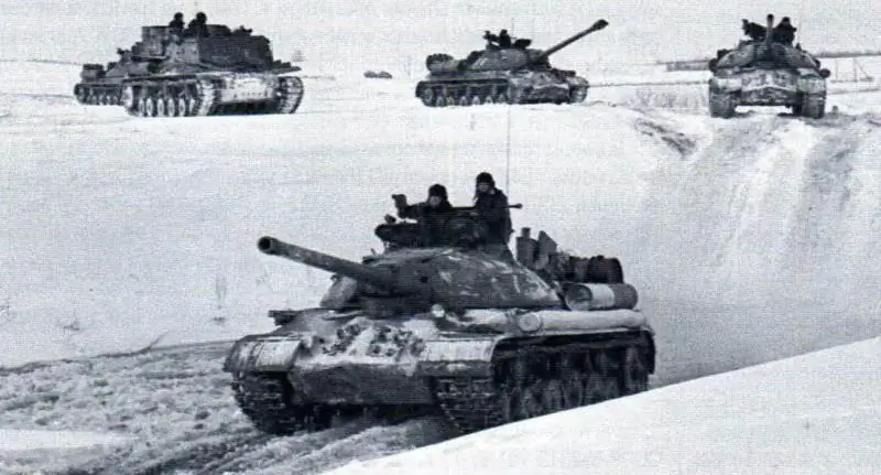
Tanks IS-3 in the exercise. The muzzle brake is removed on the first two vehicles. 1950s Combat weight - 46 tons; crew - 4 people; weapons: cannon - 122 mm, 1 machine gun-7, 62mm, 1 machine gun-12, 7mm; armor protection - anti-shell; engine power - 382 kW (520 hp}; maximum speed - 40 km / h.
The production of IS-3 tanks with an improved electric drive for turning the turret was organized in accordance with the decree of the Council of People's Commissars of the USSR No. 3217-985 of December 30, 1945 (order of the NKTP No. 8 of January 17, 1946). The design of the electric drive was developed by the ChKZ design bureau in conjunction with the plant No. 255 by the People's Commissar-Transmash according to the Leonardo principle in combination with the command tower control device proposed by the Experimental Plant No. 100. The installation of the drive on the first 50 IS-3 tanks was carried out by ChKZ in March 1946. From April 1 of the same year, an electric turret rotation drive with commander's target designation was installed on all manufactured vehicles.
Work to increase the tank's security on the battlefield was carried out in the direction of enhancing its protection against cumulative shells (grenades) and mine resistance, as well as creating a fire-extinguishing installation (PPO system).
In order to increase the mobility of the machine, studies were launched to improve the power plant (increase the reliability of the engine, the efficiency of the cooling system, development and testing of air cleaners with automatic dust removal, a steam-dynamic heater). We started to create an electromechanical transmission (Object 707) and tracks of high wear resistance - not less than 3000 km.
During the operation of the IS-3 tanks of 1945 release, the engine overheating was revealed in conditions under which the engines of the IS-2 tanks worked normally. Conducted at the end of 1945comparative field tests of the IS-2 and IS-3 tanks confirmed this fact.
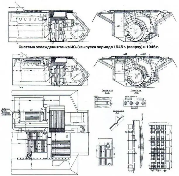
The cooling system of the engine of the IS-3 tank differed from the cooling system of the IS-2, mainly in the design and size of the air duct (especially the inlet and outlet of the cooling air), as well as the design of the air-oil coolers, the ChKZ design bureau made a number of changes in the design of the engine cooling system tank IS-3 and introduced them into serial production on tanks produced in 1946. Comparative field tests of the vehicle, which took place in the same year, confirmed the effectiveness of the measures taken.
In the IS-3 tanks of the last year of production, unlike the cars of the first series, two air-oil radiators were installed, located in front of the fans, instead of four air-oil radiators mounted behind the fans. This made it possible to obtain large internal sections of the air path of the engine cooling system by reducing the height of the internal fuel and oil tanks. The exhaust pipes have been streamlined and the configuration of the air fan headers has been improved. In addition, recommendations were given for the placement of the landing party on the vehicle in the summer (at an ambient temperature of +20 - 30 ° C), since its location on the roof of the MTO (inlet louvers for cooling air) under high engine loads could lead to its rapid overheating. …
As for the electromechanical transmission for the IS-3 tank, the requirements for it are the head of the GBTU of the USSR Armed Forces, Lieutenant General of the Tank Forces B. G. Vershinin approved it on December 16, 1946. Through its use, it was supposed to improve the dynamic qualities of the tank, apply an automated control system, and more fully realize the power of the diesel engine.
The transmission was supposed to provide:
- an increase in the average speed of the tank in comparison with a mechanical transmission;
- ease and simplicity of control of the tank;
- the acceleration time of the tank to the maximum speed is 30-40% less than the acceleration time for a tank with a mechanical transmission;
- the speed of movement of the tank in the range from 4 to 41 km / h with its smooth regulation;
- turning the tank with any radius at various speeds, with the least loss of power spent on turning;
- overcoming by the tank ascents the same as with a mechanical transmission.
However, most of these works in connection with the withdrawal from production of the IS-3 were never completed, but continued in relation to the new heavy tank IS-4. In addition, in the process of intensive operation of the IS-3 tank in peaceful conditions, a number of design errors made in its design were additionally revealed.
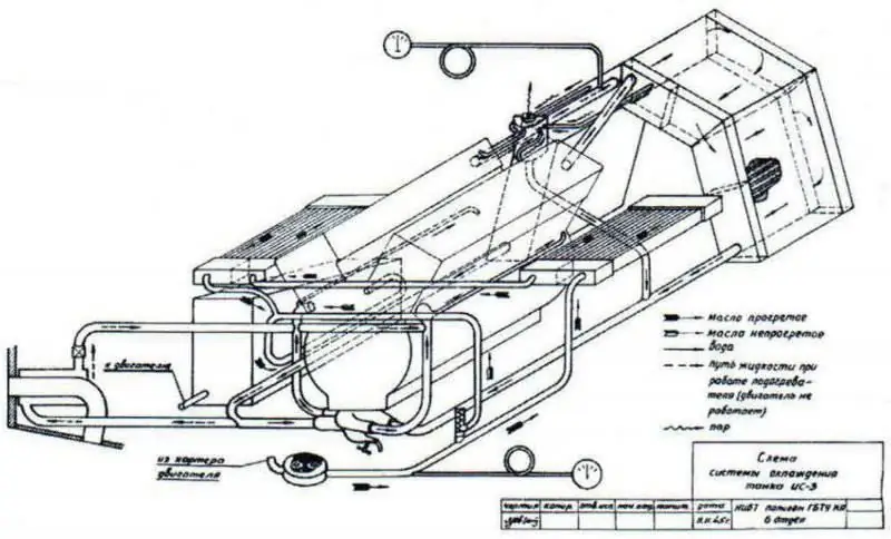
Scheme of the modified cooling system of the IS-3 tank release in 1946.
One of the significant defects of the machine was the insufficient rigidity of the body in the MTO area, which led to a violation of the alignment of its units. So, for example, not a single tank produced in 1946 passed the warranty tests for 300 and 1000 km of run. In the same year, ChKZ received a stream of complaints from the troops in connection with the failure of engines. During the tests of six IS-3 tanks, malfunctioning of the vertical roller of the fuel pump drive of the V-11 engine was revealed due to the destruction of the ball bearing separator of this roller. As a result, ChKZ took appropriate measures to improve the reliability of its operation (the ball bearing was replaced with a sleeve bearing on engines of subsequent production).
In addition, in the process of long-term operation of the machines, cracks began to appear not only in the welded seams of the hull, but also in the casings of the cast towers (in the area of the gun installation, as well as in the zygomatic and other parts). Low strength of welded joints of the IS-3 body was confirmed
The results of shelling tests in 1946 at the NIIBT test site of five buildings made by the Chelyabinsk plant No. 200 and the Uralmash-plant were also shown. For a more detailed study of the defects of the IS-3 tanks, the plant sent brigades of qualified designers and operators to the military units.
In accordance with the decree of the Council of Ministers of the USSR No. 3540 of March 30, 1948 and the order of the USSR Ministry of Transport Engineering No. 81 of March 31, 1948, at ChKZ and LKZ, in a short time, they carried out a large research work to identify the causes of the destruction of bearings and crankshafts of diesel engines of tanks IS-3. First of all, the specialists of the factories analyzed all the material on the defects of the engine-transmission unit, received from military units for the period from 1945 to 1948, and also comprehensively studied reports on special tests of IS-3 tanks at the NIBT proving ground in Kubinka.
On the basis of the material received, the ChKZ design bureau (as the head of the car), in pursuance of the decree of the Council of Ministers of the USSR No. 2312-901 of June 10, 1949, developed a number of measures to eliminate design flaws (UCN). They were carried out and tested by testing two IS-3 tanks, and then performed on ten more machines, modernized by the plant and presented for military trials in August 1949. According to the appendix to the decree, the IS-3 tank UCN measures were implemented in two stages.
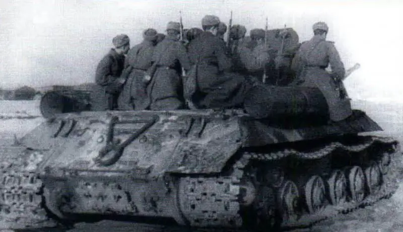
Placing the landing on the IS-3 tank. Tests at the NIIBT proving ground, 1946
The activities of the first stage of modernization included:
- development and manufacture of a new design of engine mounts, which ensured an increase in their rigidity and prevented them from loosening;
- improving the stability of the engine mount and sub-frame;
- replacement of a manual booster pump with a booster unit with an electric motor;
- bringing the crankshaft bearings of the V-11 engine to a conditional state;
- introduction of a valve in the oil tank;
- installation of fans of improved design;
- improving the fastening of the main clutch on the crankshaft due to its landing on the cones;
- the introduction of the centering of the engine and gearbox with the measurement of the end and radial clearance in two planes for both units;
- the use of a semi-rigid connection between the driven shaft of the main clutch and the longitudinal shaft of the gearbox;
- changing the fastening of the front neck of the gearbox housing by using long pins or bolts, removing the hinge on the left side of the traverse with strengthening its attachment to the bottom by introducing the middle support (to improve the installation of the gearbox);
- reinforcement of the rear support of the gearbox.
In addition, the plant strengthened the cannon lifting mechanism bracket, the turret plate, equipped the tanks with TBM steel tracks, transferred the starter crown from the fan to the semi-rigid coupling.
Military tests of ten modernized IS-3 tanks were held in the 4th Kantemirovsk division from September 2 to October 16, 1949. The test results showed that the measures implemented to eliminate structural defects carried out by ChKZ and aimed at improving the operational qualities of the machines ensured the normal operation of the units and units. However, the reliability of the IS-3 tanks was still insufficient, since during the tests there were cases of failure of gearboxes, final drives, leaks of oil coolers, etc.
For the final refinement of the design of the IS-3 tanks, the factories were asked to immediately work out all the measures that completely eliminated the identified defects, while paying special attention to improving the gearbox, final drives, layering and oil coolers. All innovations were to be implemented on three tanks, the tests of which (in accordance with the decree of the Council of Ministers of the USSR No. 2312-901 of June 10, 1949) should have been completed before January 1, 1950.
By the indicated date, ChKZ completed work on the second stage of modernization, which included the finalization of the design of the gearbox, anti-aircraft machine gun and road roller seals. Taking these measures into account, three tanks were manufactured and tested for the guaranteed mileage, according to the results of which the plant completed the final development of the drawing and technical documentation for the modernization.
Modernization of the IS-3 tanks, which came from military units, was carried out at ChKZ (from 1950 to 1953) and LKZ (from 1950 to 1954) in accordance with the decree of the Council of Ministers of the USSR No. 4871-2121 of December 12 1950 Modernization of machines during this period by manufacturers was carried out without changing the brand of the machine.
The IS-3 tanks supplied to the factories from the troops for carrying out the UKN should have been fully equipped, not requiring major repairs, but at the same time, machines that had worked out the warranty period of service (1000 hours) were allowed. However, these requirements were often not met by the GBTU of the Armed Forces, and the factories received tanks in a disassembled state, subject to major repairs. Therefore, LKZ and ChKZ were forced, in parallel with the UKN, to carry out initial overhaul and refurbishment, while replacing up to 80% of all machine parts.
In November-December 1951, during the control tests of the IS-3 tank at the LKZ after the implementation of the UKN (in accordance with the decree of the Council of Ministers of the USSR No. 4871-2121), a defect was again discovered associated with a breakdown of the drive parts of the fuel pump of the V-11M engine, which did not show itself when testing ten tanks in 1949 (the fuel pump drives were working properly). These breakdowns took place during subsequent tests of five IS-3 tanks at the LKZ, and later during the operation of vehicles in the army.
Due to the presence of a recurring defect associated with the destruction of the engine fuel pump drive, the acceptance of the IS-3 tanks after the ICT at the LKZ and ChKZ was terminated until the causes of the defect were clarified and measures were developed to eliminate it. At the same time, ChKZ stopped accepting the V-11M engines.
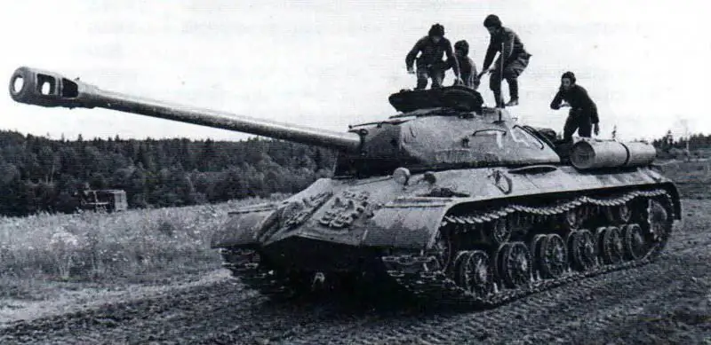
Tank IS-3 after the first events on UKN, Naro-Fominsk, August 1956
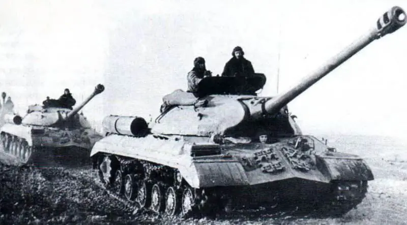
Tanks IS-3 on the march (vehicles after the events on UKN 1952), 1960-egg.
The repeated destruction of the engine fuel pump drive was explained by the fact that the UKN measures made it possible to operate the IS-3 tanks at higher average speeds (about 25 km / h) with the maximum engine load, the specific power of which did not exceed 7, 72 kW / t (10, 5 hp / t). Under these conditions, when shifting from a lower gear to a higher gear, the engine was at the resonant crankshaft speed for a longer time, which led to the defect'78.
Tests of ten IS-3 tanks in 1949 took place in other road conditions, when average speeds did not exceed 10-15 km / h. At the same time, the engines of the machines functioned outside the danger zone, which ensured the normal operation of the drives of their fuel pumps.
The commission appointed by the Ministry of Transport Engineering, as well as attracted specialists from Leningrad institutes and NIID came to the conclusion that the defect in the fuel pump drive can be eliminated by giving the drive clutch additional elasticity and connecting additional masses to the fuel pump. The specialists of ChKZ came to the same conclusion. As a result, several versions of elastic couplings were manufactured to replace the rigid serial coupling, of which one was chosen in the course of bench tests - the ChKZ design, which was named ChKZ-45.
In the period from March 5 to March 25, 1952, in the Leningrad region, an interdepartmental commission tested four IS-3 tanks, the drives of the fuel pumps of the engines of which had elastic couplings. Failure of the drives of the fuel pumps of the engines was not noted, however, the tests had to be stopped due to the destruction of the trailed connecting rods in the engines of three machines. According to the conclusion of the commission, the reason for the destruction of the trailed connecting rods was the prolonged operation of the engine at the maximum torque mode, which coincided with the zone of the resonant crankshaft rotation frequencies of this type of engine.
In order to determine the reliability of the fuel pump drive and engine connecting rods in the period from April 14 to May 23, 1952.in the Chelyabinsk region, the interdepartmental commission again carried out sea trials (for 200 hours of engine operation and 3000 km of run) of six IS-3 tanks with elastic couplings in the drives of the engine fuel pumps, a changed fuel feed angle and in compliance with the instructions for operating the machines (time limit operation in resonance mode). At the same time, serial V11-ISZ engines were installed on two tanks, on the third and fourth - engines with a dual-mode regulator without a fuel supply corrector, on the fifth and sixth - engines without a fuel supply corrector; the engine torque was adjusted to 2254 Nm (230 kgm) at a crankshaft speed of 1300 rpm '; the maximum power was 415 kW (565 hp) at a crankshaft speed of 2000 min.
To participate in the tests from the military units, driver mechanics of various qualifications were attracted - from beginners to driving masters.
During the tests, the tanks passed from 3027 to 3162 km, all engines reliably worked for 200 h5. There were no cases of destruction of parts of drives of fuel pumps and trailed connecting rods of engines. Thus, the measures taken, subject to the operating instructions, ensured the reliable operation of the engines for the specified time. Nevertheless, after the tanks worked out the warranty period, there were isolated cases of failure of the transmission units and the engine cooling system, according to which the plant carried out measures that ensured a longer and more reliable operation of the IS-3 tank as a whole.
The failure of individual transmission units and engine cooling systems of the IS-3 tanks during these tests was due to the fact that they took place in high dust conditions. Due to the lack of dust shields on the fenders for 5-6 hours of MTO operation and the tanks as a whole were clogged with dust so much that the engines quickly overheated, and due to the dustiness of the brake bridges and rods, the main clutches did not turn off, the gears were poorly shifted in gearboxes - as a result, the cars lost control. For this reason, the average speed of movement decreased, and transmissions broke down prematurely.
To eliminate these shortcomings, WGC ChKZ developed a new design of dust shields (similar to the prototype 730 Object tank)
for the fenders of the car, which began to be installed on July 1, 1952 (the release of the shields was organized at the plant No. 200).
The reliability of the PMP brake bands (the controllability of the machine depended on them) was increased by changing the design of the brake bands and their installation in the tank. They were introduced into a series at industrial plants from June 1, and at military repair plants - from July 1, 1952.
Based on the test results of six IS-3s in the spring of 1952, the commission came to the conclusion that it is possible to resume acceptance of tanks of this type from UKN at LKZ and ChKZ and on the need to replace the rigid serial coupling of the engine fuel pump drive with an elastic coupling ChKZ- 45. As a result, acceptance of tanks at the factories (as well as the V-11M diesel engine at ChKZ) was resumed on May 30, 1952.
At the same time, the command of the BT and MB of the Soviet Army was offered during 1952-1953. to conduct comprehensive military and field tests in various climatic conditions of ten IS-3 tanks with engines of increased power. Based on the results of these tests, together with the Ministry of Transport Engineering, it was necessary to resolve the issue of the possibility of re-adjusting all V-11M engines to a power of 419 kW (570 hp).
In December 1952, three IS-3 tanks with engines of increased power (419 kW (570 hp)) were tested at the NIIBT proving ground. However, these tests were terminated due to the failure of the gearboxes. means of the landfill, and two boxes required replacement with delivery from the LKZ by January 10, 1953. However, the question of installing high-power engines in the IS-3 tanks with the UKN remained open”9.
During all this time, the factories were constantly working out and adjusting the technical conditions for the UKN, which have not yet been finally agreed and approved with the GBTU Armed Forces. The main issue was the issue of defectation and the volume of repair of welded seams of the armored hull, as well as the issue of the permissible size of defects in the casings of cast turrets.
The flaw detection of the welded seams of the hulls at the LKZ was carried out by external inspection and only seams that had cracks or pinholes were corrected (all other seams were not subject to correction). However, GBTU VS questioned the reliability of all seams of the hull and required the correction of almost all possible manufacturing defects. An option for a stamped bottom was proposed in the case of the manufacture of new hulls for the IS-3 tanks, but this contradicted the government's decree on the implementation of the UKN, and the replacement of the bottom on the repair hulls of the tanks with stamped was deemed unnecessary. Since November 1951, in addition to the LKZ and ChKZ, plant No. 200 was connected to the repair of the hulls of the IS-3 tanks.
With regard to the repair of the casings of cast towers, the Ministry of Transport Engineering also limited itself only to the requirement of welding cracks, considering after that all towers were serviceable. In turn, the GBTU VS also put restrictions on the depth and location of the cracks, which led to the transfer of a large number of tank turrets to scrap.
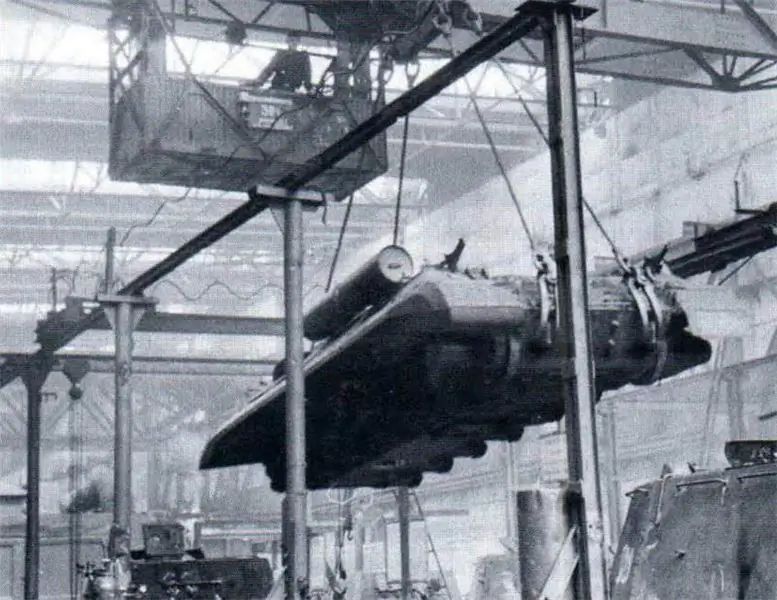
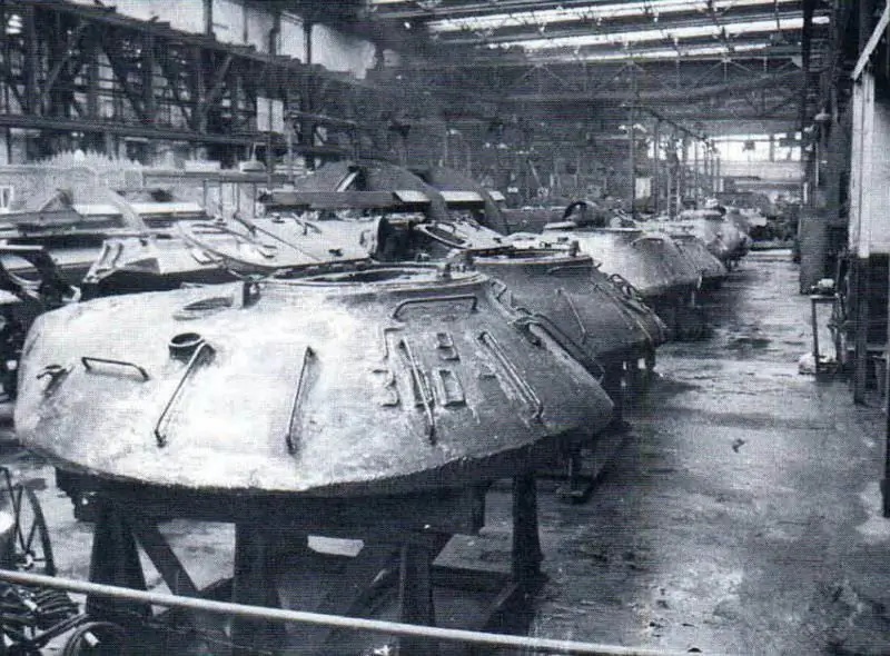
Repair of the IS-ZM tank with the UKN on 61 armored personnel carriers (Leningrad), 1960s.
According to the decree of the Council of Ministers of the USSR No. 4871-2121, the Ministry of Transport Engineering was supposed to carry out the UCN in the body of the IS-3 tank only on the sub-engine foundation, strengthening the turret plate with kerchiefs and welding the emerging cracks with austenite welding wire. Other, additional work, as a rule, included welding repair of parts and assemblies of the undercarriage, bottom and welding of cracks in the seams. Along the tower - welding of cracks. The work of LKZ in this direction in 1951 did not cause any complaints from the GBTU Armed Forces. After the repair, the tanks were successfully tested with a range of up to 2000 km.
Fault detection maps developed by LKZ and ChKZ, agreed in the middle of 1951 with military acceptance, ensured the elimination of all significant defects in welded seams (including seams with cracks and pinholes).
Until the end of their life cycle, these machines, during subsequent overhauls, were equipped with engines of standard power - 382 kWh (520 hp). In addition, the following were introduced: additional reinforcement of the torsion bar brackets (the seams were increased from 10 to 15 mm), a second seam at the bottom junction, stiffeners on the bottom were installed and other smaller reinforcements were made.
However, at the beginning of 1952, representatives of the GBTU Armed Forces put forward new requirements that led to the correction of all deviations in the quality of welded seams: in addition to removing seams with cracks, seams with increased porosity, undercuts of the base metal, minor lack of penetration or sagging, reduced dimensions and others were corrected. minor defects.
Nevertheless, the technical documentation for the repair of the hulls and turrets of the IS-3 tank was worked out by ChKZ on the basis of a joint decision of the Ministry of Transport Engineering and the command of BT and MB of the Soviet Army dated March 29-31, 1952 and sent to the LKZ addresses in April of the same year. and plant number 200 and introduced into serial production.
In addition to welding cracks on the turrets of the IS-3 tanks, it was planned to replace the old turrets with new ones on parts of the repair vehicles. So, for example, the production of 15 new towers in the IV quarter of 1952 was entrusted to the plant No. 200. New towers were cast from 74L steel and subjected to heat treatment for medium hardness (indentation diameter according to Brinell 3, 45-3, 75). The production of the towers was carried out in a complete set with a running device according to the drawings and specifications approved for 1952, taking into account the changes adopted by the GBTU Armed Forces and the Ministry of Transport Engineering in the process of work on the UKN, i.e. with reinforced brackets for the TSh-17 gun and sight, ammunition rack mountings, etc. At the same time, in order to increase the structural strength of the GBTU VS towers, it was required from the ChKZ design bureau to weld the sub-base of the tower from the outer and inner sides, to strengthen the weld sections of the welding of the support brackets of the gun trunnions and the support strips of the removable hatch cover for mounting the gun.
In addition, it was supposed by September 15, 1952, to test the quality of the welding of cracks during the UKN, to test by firing two IS-3 towers (high and medium hardness), which had the greatest number of cracks in the area of the weapon installation, in the cheekbones and other parts as in length and depth, including through cracks.
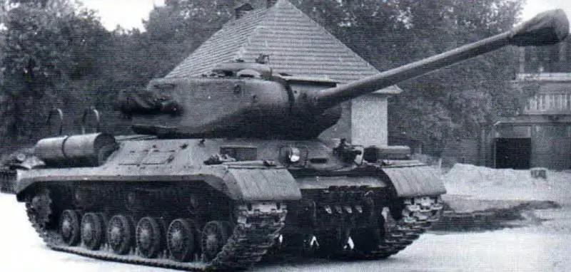
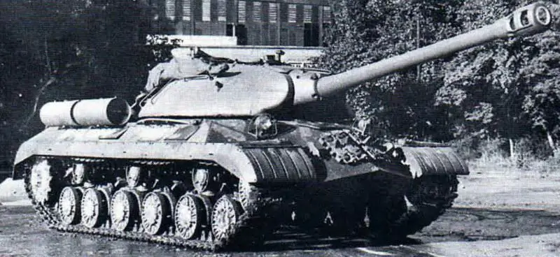
Upgraded tanks IS-2M and IS-ZM, issue 61 BTRZ (Leningrad).
The new towers were to be supplied to the GBTU of the Armed Forces fully equipped (with the exception of the artillery system and radio station) parts, assemblies, electrical devices, turret rotation mechanism, TPU, etc. so that in the event of mobilization in military units, it would be possible to quickly replace the old towers on the IS-3 tanks.
In addition to the towers, in November 1952, the question was raised of replacing the 10RK-26 radio stations installed in the IS-3 tank with the 10RT-26E radio station, since the placement of the 10RK-26 radio station greatly impeded the actions of the tank commander and loader. It turned out to be impossible to place it more conveniently in the turret of the tank, since it was not unlocked, and the configuration and internal volume of the turret did not allow changing its location to a more convenient one. In addition, the 10RK-26 radio stations are already outdated in terms of their operation time, and their warranty period has expired. Almost every radio station required a major overhaul. The replacement of radio stations began in 1953 (the volume of the first batch of 10RT-26E radio stations was 540 sets).
At the same time, work on further improving the reliability of individual components of the IS-3 tank did not stop at ChKZ. So, for example, in 1953 on one of the prototypes (factory # 366) a V11-ISZ diesel engine with an anti-vibration device designed by factory # 77 was installed for sea trials. During the tests, the tank traveled 2,592 km, and the engine ran for 146 hours without any remarks. Other advanced experimental units and assemblies were also tested on the machine.
Subsequently, measures to modernize the tank were carried out by repair plants of the USSR Ministry of Defense: 7 BTRZ (Kiev), 17 BTRZ (Lvov) and 120 BTRZ (Kirchmezer, GSVG), as well as 61 BTRZ (Leningrad).
Taking into account the experience of modernizing the IS-3 tank, the management of the GBTU Armed Forces made a decision, starting in 1957, to carry out the UKN during the overhaul and for the IS-2 tanks, as they had become less reliable in operation. The volume of the UKN on the instructions of the Department of Repair and Supply (URiS) of the GBTU of the Armed Forces was developed by the repair plants of the USSR Ministry of Defense - 7 BTRZ (Kiev), 17 BTRZ (Lviv) and 120 BTRZ (Kirchmezer, GSVG). At the same time, the task was completed not only to strengthen individual weak units, but also to equip the machine with more modern equipment, as well as to unify a number of units and devices with other tanks (for example, installing a V-54K-IS diesel engine, a nozzle heater, new air cleaners with ejection dust removal from bunkers, a gearbox with an oil cooling system in it, an electric starter, a prismatic observation device for a driver, electrical control devices, a driver's night vision device, a new radio station, an increase in gun ammunition, etc.). All these activities were implemented in 1957-1959. in prototypes that have passed long run tests in the GSVG.
Since 1960, when carrying out measures for the UKN at the tank repair factories of the Ministry of Defense, the modernized version of the IS-2 tank was named IS-2M. From the end of 1962, the brand was also changed for the modernized version of the IS-3 tank to the IS-ZM. On the basis of the IS-ZM tank, the tank repair plants of the USSR Ministry of Defense produced the command version - the IS-ZMK. Some of the IS-2M tanks were converted into tank tractors during the overhaul. The modernization of the IS-2M and IS-3M tanks was carried out by tank repair plants until the end of the 1970s.
In 1946, a new heavy tank IS-4 entered service with the Soviet Army, the development of which, like the IS-3 tank, began during the Great Patriotic War. This combat vehicle was created in accordance with the IT requirements for a new heavy tank in the last years of the war, and, unlike the IS-3, was not an upgrade of the IS-2. The new tank was developed as an offensive weapon to break through the prepared enemy defenses and was intended to destroy enemy manpower, fire weapons, as well as to fight against his heavy tanks and artillery.
The IS-4 tank was produced at ChKZ in 1947-1949. and during serial production it was modernized with a change in brand to IS-4M. The plant manufactured a small batch of IS-4M tanks in 1951. In the same year, according to the revised technical documentation, ChKZ modernized all previously produced vehicles.
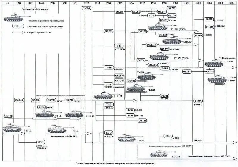
The T-10 tank, adopted by the Soviet Army in 1953, like its subsequent modifications T-10A, T-10B and T-10M, was a further development of the IS-3 tank in accordance with the concept adopted for the combat vehicles of this class. Serial production of T-10 tanks of various modifications was organized in 1953-1965. at the Chelyabinsk Kirov Plant (from May 15, 1958 - the Chelyabinsk Tractor Plant), and from 1958 to 1963 - at the Leningrad Kirov Plant, where the heavy tank T-10M ("Object 272") was produced.
Post-war domestic heavy tanks IS-4 and T-10 of various modifications were only in service with the Soviet Army and were not exported to other countries.

Along with the serial production of heavy tanks IS-4, T-10 and their modifications in the first post-war period, R&D was carried out to create a new generation of heavy tanks with increased firepower, a high level of protection and mobility. As a result, prototypes of tanks were developed and manufactured: Object 260 (IS-7), Object 265, Object 266, Object 277, Object 770 and Object 279. The experimental heavy tank "Object 278" with a gas turbine engine was not completed.
The development of heavy tanks of the period under review was characteristic:
- application of the classical scheme of the general layout with a longitudinal engine arrangement in MTO'82;
- an increase in the combat mass of vehicles up to 50-68 tons in connection with the strengthening of their protection against weapons of mass destruction and powerful anti-tank weapons of the enemy;
- an increase in the maximum thickness of the armor of the frontal part of the tank hull up to 305 mm;
- increasing the maximum speed to 42-59 km / h and increasing the range on the highway to 200-350 km;
- the growth of the caliber of the gun up to 130 mm and machine guns - up to 14, 5 mm;
- increase in engine power up to 772 kW (1050 hp);
- adaptation of serial tanks to operations in conditions of the use of nuclear weapons.
An important feature of the development of heavy tanks was the search, development and implementation of original layout and design solutions, some of which served as the basis for further improvement of different types of armored weapons in terms of purpose and combat weight. These most important decisions included:
- in terms of firepower - 122- and 130-mm rifled tank guns with an ejection device for removing powder gases from the bore; a semi-automatic cassette-type loading mechanism for a 130-mm cannon, a hydrostatic drive to control the turret rotation mechanism and an optical rangefinder (Object 277); stabilization of the aiming line in two planes (tanks T-10B, T-10M, "Object 265", "Object 277", "Object 279", "Object 770"); remote control of a machine-gun mount (Object 260); the use of the 9K11 Malyutka ATGM as an additional weapon (Object 272M);
- in terms of security - cast armored hull ("Object 770"), bent side plates of the hull, automatic PAZ and PPO systems, TDA (T-10M tank), anti-cumulative shield ("Object 279");
- in terms of mobility - diesel type B-2 with supercharging, ejection cooling system, planetary gearbox, swing mechanism of "ZK" type, hydraulic servo control system, lever-piston hydraulic shock absorber, beam torsion bar suspension, equipment for underwater driving (T-10M tank), gas turbine engine ("Object 278"), hydromechanical transmission ("Object 266", "Object 279", "Object 770"), hydropneumatic suspension, road wheels with internal shock absorption, steering wheel drive of the tank turning mechanism ("Object 770").
In addition, the system for blowing compressed air of the barrel bore, radar rangefinders (including those coupled with the sight), diesel engines with a capacity of 735-809 kW (1000-1100 hp), hydraulic suspension, relaxation hydraulic shock absorber, four-track propulsion, mounted engineering equipment (floating craft and mine trawls).
In addition to the design bureaus ChKZ (ChTZ), LKZ and the Chelyabinsk Experimental Plant No. 100, VNII-100, created in 1948 on the basis of the Leningrad branch, was directly involved in the development of heavy experimental tanks, as well as testing and fine-tuning of production vehicles, their components and assemblies. Pilot Plant No. 100'83.
Initially, on the basis of the decree of the Council of People's Commissars of the USSR No. 350-142 of February 12, 1946 on the deployment of work on the design and manufacture of prototypes of the Object 260 tank by order of V. A. Malyshev, a merger of the teams of two design bureaus was carried out - the OKB of the branch of plant No. 100 and the Department of the Chief Designer (OGK) of the tank production of LKZ. Team leaders, design engineers and maintenance personnel were united in accordance with the qualifications and specialties of each of them and regardless of their formal subordination. The newly formed design team consisted of 205 people (of which: management staff and design engineers - 142, technicians - 28, copiers and draftsmen - 26 and service personnel - 9 people). Most of the employees had extensive experience in the design and manufacture of tanks.
Due to the fact that the main cadres of highly qualified designers and production tankers at that time were concentrated in the branch of plant No. 100, the production activity of which was closely related to the LKZ, the costs of design and implementation of experimental work between the two organizations were distributed in a ratio of 60/40 of the total, respectively.
In May 1946, a special group was organized as part of OGK, which was engaged in the design of stands and non-standard equipment for the test shop (ISC-100). The main task facing this group was to promptly resolve issues arising in the design of a new heavy tank ("Object 260"), test individual components and assemblies of the vehicle. Therefore, one of the most important areas of work of the staff of the branch of plant No. 100 was the creation of its own experimental research and laboratory base.
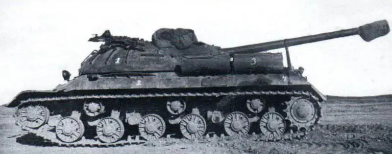
Tank IS-3, prepared for research on MTO radiation. NIIBT polygon, 1947
To accommodate all research laboratories and stands on experimental tank topics ISC-100, part of the building of the Branch of Plant No. 100 was taken, which was a complex of ten mine boxes with consoles.
In June 1946, at the branch of plant No. 100, they established their own experimental and production base consisting of a mechanical, assembly, testing and tool shops, a department of the Chief Technologist, and a department of the Chief Mechanic with auxiliary services. Consistent work has begun to expand this base, to staff the shops with qualified workers and engineers, to expand and improve the composition of equipment.
During 1946, the organization of the Leningrad branch of Plant No. 100 was completed. The main cadres of designers, technologists, testers and workers moved to Leningrad, where, as part of the mechanical, assembly, testing and auxiliary shops with a full set of metal-cutting equipment and with a large number of stands and laboratories, they created their own production base for experimental work. By the end of the year, the personnel of the Leningrad branch (together with OGK LKZ) totaled 754 people.
8 in accordance with the proposal of V. A. Malyshev from January 1, 1947. The Department of the Chief Designer for Heavy Tanks at the LKZ and OKB at the branch of plant No. 100 was merged into one Department of the Chief Designer at the branch of Plant No. 100. At the same time, the Department of the Chief Designer for Heavy Tanks at LKZ was abolished. The next step was the creation of the All-Union Research Tank and Diesel Institute No. 100 (VNII-100) of the USSR Ministry of Transport Engineering on the basis of the Leningrad branch of plant No. 100 (on the territory of the LKZ). Decree of the Council of Ministers of the USSR No. 2026-795 on its organization was signed on June 11, 1948 (order of the Ministry of Transport Engineering No. 180 of June 16, 1948).
On March 9, 1949, the Council of Ministers of the USSR approved the priority measures to ensure the work of VNII-100. The leadership of the Ministry of Transport Engineering and the Institute was charged with the obligation to carry out R&D along with research and development, as well as in cooperation with the LKZ shops to produce prototypes according to their projects. Already on March 19 of the same year, Deputy Chairman of the Council of Ministers of the USSR V. A. Malyshev, by his order, established the subordination of Institute 1 to the Main Directorate of the Ministry, appointing Zh. Ya. Kotin, retaining his position as chief designer of the LKZ.
On June 4, 1949, order No. 1 of the director was issued on the beginning of the VNII-100 activity. In accordance with the approved management scheme, the institute had five design, ten research and general institute departments, an experimental production base (mechanical, tool and assembly shops), auxiliary services and a tank testing station. The initial staff of VNII-100 consisted of 1,010 people.
Until the middle of 1951, VNII-100 performed a dual function - both at the industrial and factory levels. However, OCD prevailed over research topics. The interests of LKZ were put above the branch ones. In accordance with the order of the Council of Ministers of the USSR No. 13081рс of July 31, 1951, a Special Design Bureau for Heavy Tanks (OKBT) with an experimental base was organized at the LKZ. In addition to LKZ employees, the OKBT included engineering and technical workers, employees and workers (in the required number) transferred from VNII-100 in accordance with the order of the Ministry of Transport Engineering No. 535 dated August 10, 1951. Zh. I AM. Kotin. With his transfer to LKZ, P. K. Voroshilov, and the deputy director for research and development - VT. Lomonosov'86.
At the same time, ChKZ was transferred to Experimental Plant No. 100 as an experimental base by order of the Council of Ministers of the USSR No. 13605рс dated August 4, 1951. The design bureau at ChKZ (ChTZ) was successively led by N. L. Dukhov, M. F. Balzhi and P. P. Isakov.
Employees of the NTK GBTU (UNTV), the Academy of Armored Forces named after V. I. IN AND. Stalin and NIIBT test site.
It should be noted that a number of R&D projects related to improving the combat and technical characteristics of post-war heavy tanks were carried out using the IS-2 and IS-3 of the military year of production and after the implementation of the UKN measures.
So, for example, back in 1946 at the range of the Leningrad Higher Officer Armored School (LVOBSH) named after. Molotov, in the period from August 20 to September 5, two captured German tank rangefinders were tested: a stereoscopic horizontal base type (base 1600 mm) and a monoscopic vertical base type "Kontsidenz" (base 1000 mm), installed on the IS-2 and IS-3 tanks, under the program of Artkom GAU VS and NTK GBTU VS'87. Tank IS-2 stood out LVOBSH them. Molotov, tank IS-3 - LKZ. The installation of rangefinders in tanks was carried out at LKZ in the period from 10 to 20 August 1946.
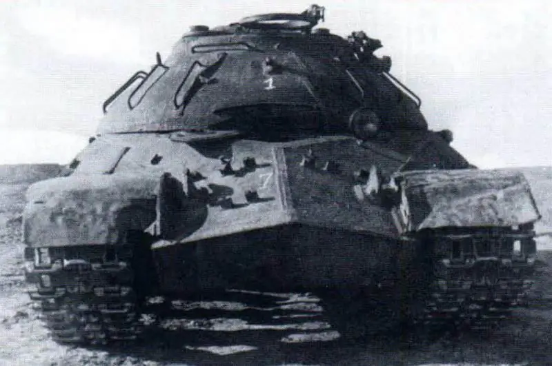
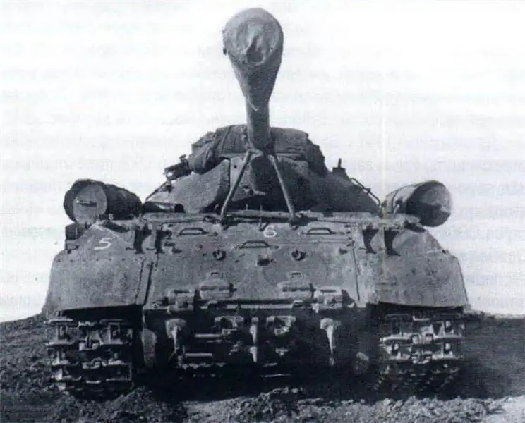
Tank IS-3, prepared for research _ on MTO radiation. NIIBT polygon, 1947
The tests were carried out in order to identify the effectiveness of shooting using rangefinders, to determine the advantages of a particular type of rangefinder, as well as to select the type of rangefinder for its use in tanks and self-propelled guns. As shown by the test results, these rangefinders provided range measurement and cannon firing at distances from 400 to 6000 m.
In 1947, in order to study the energy characteristics of tanks in the period from September 11 to October 4, at the NIIBT proving ground, samples of armored vehicles, including the IS-3 heavy tank, were tested for thermal radiation. The work was carried out jointly by IRiAP and NII VS. As shown by the test results, the IS-3 tank had the best design and location of exhaust pipes compared to other vehicles (T-44, SU-76, BA-64, American light tank M-24). When the machines were moving, the heated parts were exhaust pipes, armor plates located near these pipes, as well as armor plates located next to the radiators of the engine cooling system. So, for example, the heating of the exhaust pipes of the IS-3 tank to 85'C occurred 50 minutes after starting the engine, then the temperature of the pipes at idle speed reached 10O'C, while the tank was moving - 220-270'C, while the value of the maximum intensity radiation was 127 W / sr.
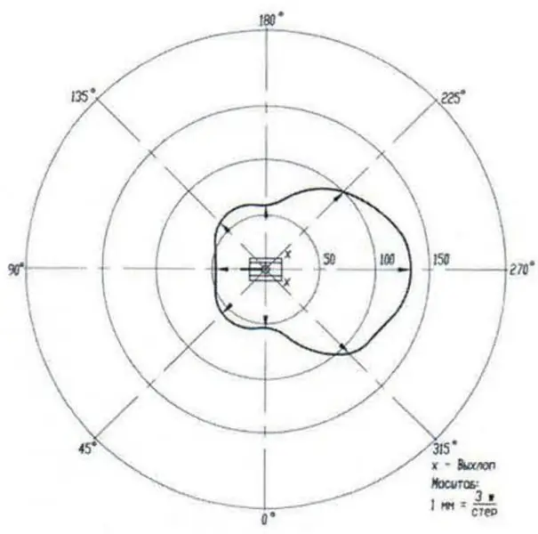
Polar radiation diagram of the IS-3 tank.
The detection of tanks by their thermal radiation was carried out using the Leopard 45 heat block, while the maximum detection range was up to 3600 m. Based on the results of the studies, conclusions were drawn about the need to use shielding of exhaust pipes and their rational placement on machines (like an IS tank -3), since the direction and intensity of thermal radiation depended on their location.
Taking into account the results of tests of captured optical range finders in 1946 at the NIIBT proving ground in the period from March 30 to August 10, 1948, tests of domestic range finders were carried out on the IS-2 tank: the horizontal base PCT-13 and the vertical base PCT-13a of the design of the State Optical Institute named after V. I. Vavilov.
The PTTs-13 rangefinder (800 mm base, 10 "magnification) was mounted in a mounting layout (steel armored box) on the roof of the commander's cupola, while the MK-4 commander's observation device and the DShK anti-aircraft machine gun turret were removed. there was a rectangular hole inside the commander's cupola at the base of the steel box. Mounting the rangefinder in the installation layout (in special trunnions with rubber shock absorbers) provided the ability to observe and measure ranges to the target with elevation angles from -5 to +16 '. Rangefinder finder, which had a field of view of 12 'and an increase of 4 ", made it possible to recognize a target at a distance of more than 2000 m. However, the fixing of the rangefinder in the mounting device was unreliable. When the tank was moving or when the engine was idling, there was a strong vibration in the lower part of the field of view, which made it impossible to measure the range. When firing from short stops, the range was determined with the engine turned off. Nevertheless, the number of targets hit when firing from a standstill and short stops when using the PTC-13 rangefinder was, on average, 2 times greater than with an eye measuring range, and the time spent on firing and hitting a target was less (when shooting from a standstill - 104 s instead of 125 s, with short stops, respectively, 80 and 100 s). Along with the IS-2 tank, the installation of the PTC-13 rangefinder in the IS-3 tank was recognized as possible. When installing the rangefinder, the height of the car increased by 180 mm.
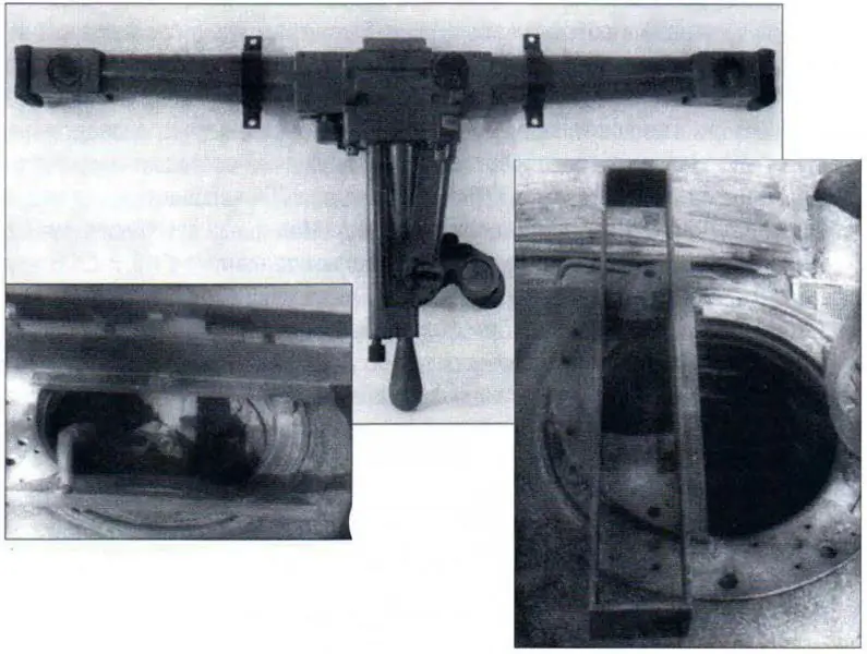
Rangefinder PTTs-13. Installation of the PTC-13 rangefinder in the commander's cupola of the IS-2 tank. Installation layout (armor protection) of the PTTs-1 3 rangefinder (cover removed) on the commander's cupola of the IS-2 tank.
The PTTs-13a rangefinder (base - 500 mm, magnification - 10 ) was mounted in the ball support of the mounting plate, which was mounted instead of the standard loader viewing device. The rangefinder was inserted into the ball bearing from below, from the tank turret, and held in it by three rollers. The ball bearing provided free guidance of the rangefinder in all directions and the installation of the dividing line perpendicular to the target lines. The disadvantages of the rangefinder included the imperfection of the method for measuring the range - by aiming the center of the dividing line on the target and aligning the horizontal lines of the image into a single whole by tilting the rangefinder. In addition, the rangefinder did not have mechanisms for alignment in height and range, and the presence of three exit pupils (of which only the middle one was a working one) made observation difficult. The two extreme ones, when working with a rangefinder, interfered with observation (especially in low light). The fixing of the rangefinder with the help of three rollers was unreliable (in the process of work, there were cases of the rangefinder falling out).
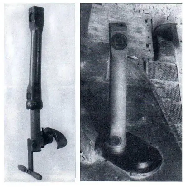
Rangefinder PTTs-13a. Installation of the PTTs-13A rangefinder in the turret of the IS-2 tank.
The firing accuracy when using the PTC-13a rangefinder was higher than with the eye measuring range, but lower than with the PTC-13 rangefinder. The number of targets hit when firing from a standstill and short stops was 1.5 times higher than the number of similar targets when determining distances by eye. The average time for firing and hitting targets, respectively, was 123 and 126 s - when firing from a standstill, 83 and 100 s - when firing from short stops. Working with the PTC-13a rangefinder when installed on heavy tanks IS-2 and IS-3 (according to estimates) was difficult due to the small dimensions of the commander's turrets. In addition, the part of the rangefinder (630 mm) towering over the tank did not have any protection against being hit by bullets and shell fragments. During the tests, the PTTs-13 and PTTs-13a range finders did not provide the required accuracy when measuring the range. Nevertheless, the PTC-13 horizontal base rangefinder demonstrated the best result in terms of shooting accuracy and range measurement accuracy. The median error in measuring the ranges (expressed as% of the true distance) exceeded 4.75% for the PTTs-13 rangefinder and 5.4% for the PTTs-13a rangefinder (with an acceptable error for optical rangefinders - 4%). However, after constructive revision (increasing the base to 1000 mm, multiplicity up to 12-15x) and eliminating the identified shortcomings, the commission that carried out the tests recommended that the PTsT-13 rangefinder be submitted for further tests.
In the period from October 1 to December 10, 1948, at the NIIBT proving ground, together with the T-54 medium tank, the IS-3 tank was tested with the TKB-450A and TKB-451 installations, adapted for mounting a 7, 62-mm Kalashnikov machine gun with a curved attachment barrel and 7, 62-mm submachine gun PP-41 (arr. 1941) with a curved barrel and a PPKS sight. During the tests, the installation of the installations was carried out in a special base, which was fastened in the opening of the loader's entrance hatch. The use of these installations ensured the conduct of all-round fire and the defeat of enemy manpower in the immediate vicinity of the tank. According to the test results, the TKB-451 installation was recognized as the most convenient for use in the IS-3 tank due to its small dimensions. One of the main disadvantages of the TKB-451 and TKB-450A installations was the impossibility of loading the gun with an assault rifle (submachine gun) and sight installed and the need to move the shooter when transferring fire along the horizon. Further work in this direction in relation to the IS-3 tank was discontinued.
In order to determine the influence of some factors on the aiming rate of fire of the IS-3 tank at the NIIBT proving ground with the participation of NII-3 AAN, appropriate tests were carried out in the period from June 20 to July 12, 1951, the results of which showed that the average aiming rate of fire of the gun with great training the loader can reach 3.6 rds / min (according to TTX - 2-3 rds / min). The average time of one shot cycle was 16.5 s and consisted of removing the spent cartridge case from the hinged gun guard (2.9 s), loading the gun (9.5 s), correcting aiming and firing a shot (3.1 s), rollback and gun rollback (1, 0 s). Proceeding from this, the rate of fire from the IS-3 tank could be increased by eliminating the hanging of the spent cartridge case and eliminating the knocked-down aiming of the gun during loading.
To eliminate the hanging of the sleeve in the hinged guard of the gun, it was recommended to work out the issue of installing the reflector of the casings on the hinged guard, and to avoid knocking down the aiming and oscillations of the gun when loading it, create a slight overweight on the muzzle of the gun in the presence of a shot in the barrel chamber. A further increase in the aiming rate of fire could be ensured by introducing mechanization of the loading process.
In addition, in the process of testing, an assessment was made of the loader's access to the gun ammunition racks and the methods of loading it were worked out. The best for access were a 17-seat shell ammunition rack on the shelf of the tower in folding trays located from the fan towards the loader, and a five-seat cartridge case, located on a frame attached to the central column of the VKU, since they allowed the gun to be loaded at all readings of the tower protractor and at any vertical aiming angles of the gun.
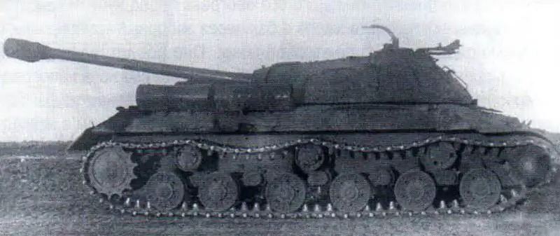
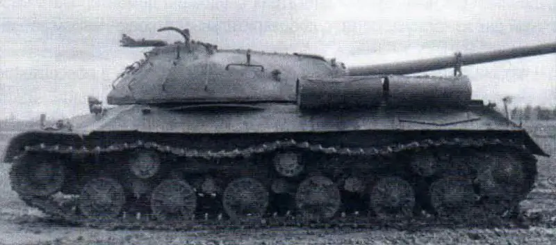
Tank IS-3 with the installation of TKB-450A and TKB-451. NIIBT polygon, 1948
The operating experience of the V-2 type engines installed on the IS-2 and IS-3 tanks showed their sufficient reliability. At the same time, despite the strict observance in the troops of the conditions for starting engines in conditions of low ambient temperatures, cases of melting of lead bronze of the main bearings were observed on these tanks. Moreover, the melting of the bearings often occurred when starting and warming up the V-2 engines at an ambient temperature of 10-15'C. These circumstances indicated that for the trouble-free operation of the V-2 engines at low temperatures on tanks that did not have reliable individual heating means, it was not enough to preheat the engine to such a thermal state, which ensured its start. For the normal functioning of the bearings of the crankshaft after starting the engine and its operation under load, a continuous and sufficient supply of oil to the rubbing surfaces of the bearings was required, which was ensured by the reliability of the oil pump.
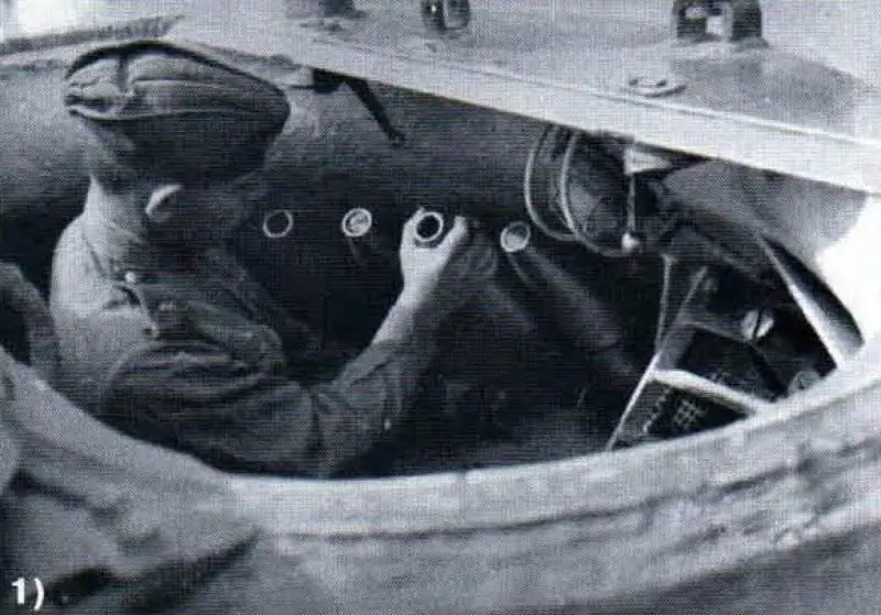
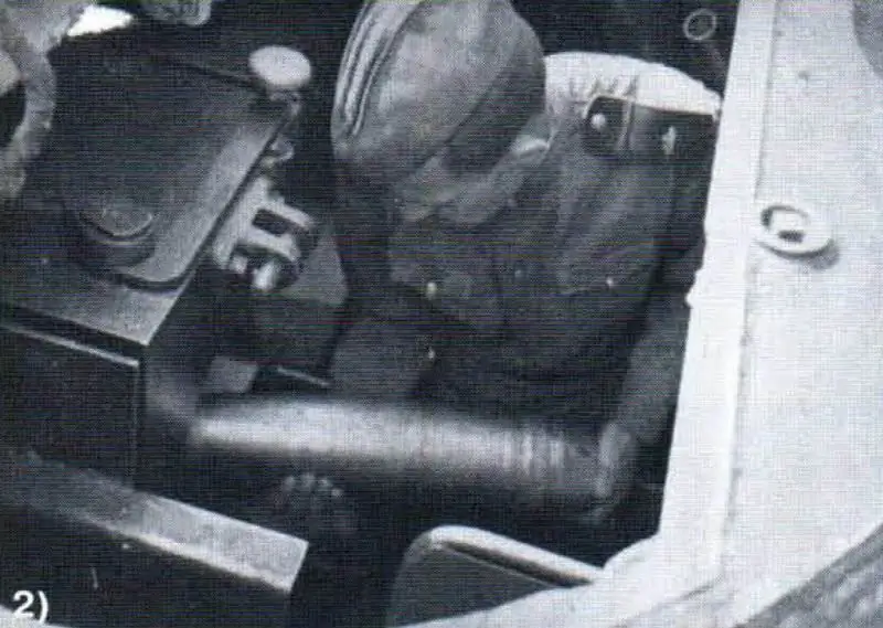
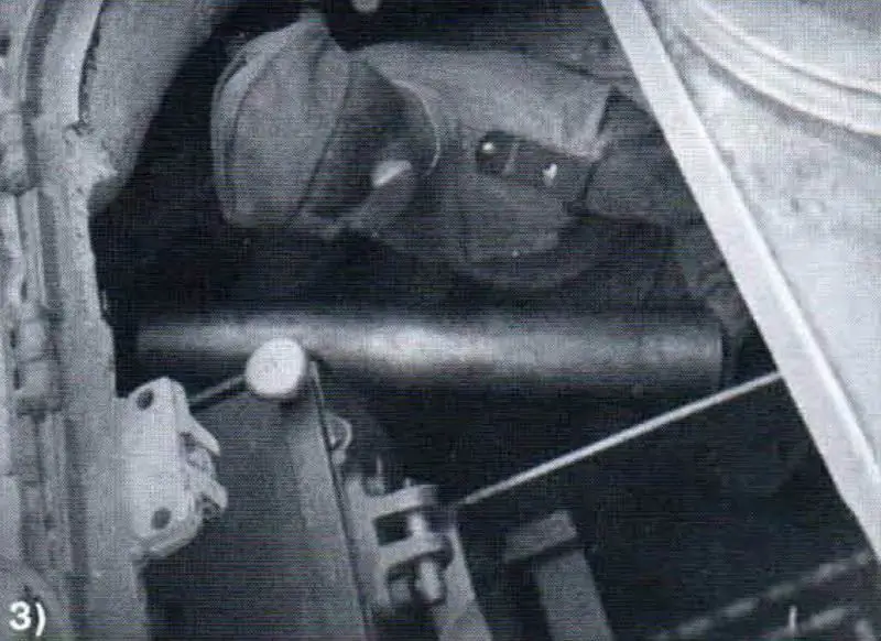
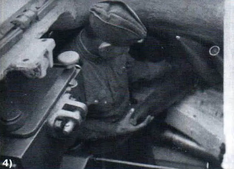
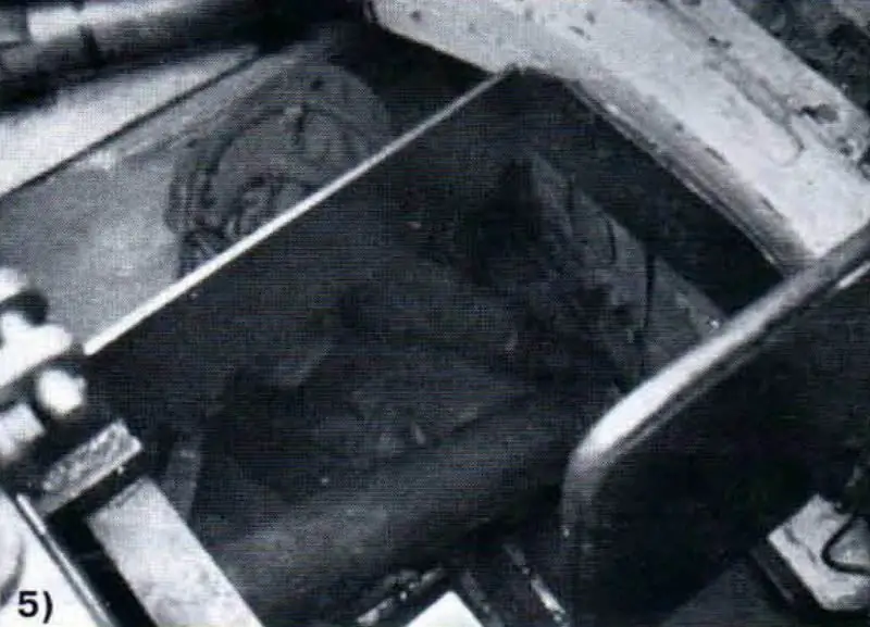
Tests of the IS-3 tank for the rate of fire. NIIBT polygon, 1951
1) removal of the second high-explosive fragmentation projectile from the 17-seat stacking of the turret;
2) the withdrawal of the second high-explosive fragmentation projectile from the 17-seat stowage to the loading line;
3) removing the first cartridge case from the 5-seat ammunition cartridge case;
4) taking out the sixth high-explosive fragmentation projectile from the 17-seat ammunition rack;
5) removing the first cartridge case from the ammunition rack located on the engine bulkhead.
Conducted in 1952-1953. Research at the NIIBT test site showed that when the V-2 engine was started at low ambient temperatures, the IS-2 and IS-3 tanks did not always provide the necessary conditions for the normal operation of the bearings, due to the presence of frozen oil in the unheated intake pipe (from the oil tank to the oil pump). In 1954, a number of design changes in the lubrication and cooling systems of these machines were developed for the IS-2 and IS-3 tanks. Thus, the specialists of the NIIBT landfill suggested removing plugs of thickened oil from the outboard pipeline without preheating it before starting the engine by pumping hot oil into the tank through the intake pipeline using a special device. It was a pipe welded into the intake pipe of the lubrication system in the immediate vicinity of the oil pump. The other end of the pipe was fixed on the motor baffle and ended with a fitting with an overhead plug. When using the device, the union nut of the hose of the oil pumping unit was screwed onto the fitting, which could be the fuel transfer pumps of the T-10 and T-54 tanks or the oil pumping unit VRZ-1.
It was possible to make this device and carry out its installation in the tank by means of the repair facilities of the military units. To retrofit the engine lubrication system, it was necessary to dismantle the oil tank from the tank hull, with the preliminary disconnection of the intake pipeline.
In addition, to reduce the preparation time and ensure trouble-free start-up of the engines of the IS-2 and IS-3 tanks at low ambient temperatures, it was proposed to pump out oil from the oil intake pipe after draining the oil from the oil tank. The experiments carried out to free the oil intake pipe from oil on these tanks using a manual or electric oil pump showed quite satisfactory results.
Tests of the IS-3 tank with the changes made to the lubrication system were carried out in a refrigerating chamber, where it was kept up to a predetermined temperature for the time required for the thermal equilibrium of the engine parts to arrive. Warming up of the engine before starting was carried out by filling the cooling system with hot antifreeze, heated to + 90-95 * С. The V-11 engine was started at a temperature of -40-42'C. To prepare the engine for start-up, it was required to make four consecutive refills of hot antifreeze to the cooling system.
The engine was reliably started in the event that the temperature of the antifreeze of the last spill (according to the standard thermometer) was not lower than + 30-35 * C. At this thermal state, the engine could be turned by hand with the help of a special luminaire and from an electric starter. After that, hot oil was pumped into the tank through the intake pipeline. The time for filling the oil into the tank through the intake pipeline was 7-10 minutes. The total time required to prepare the engine for start-up reached 110 minutes.
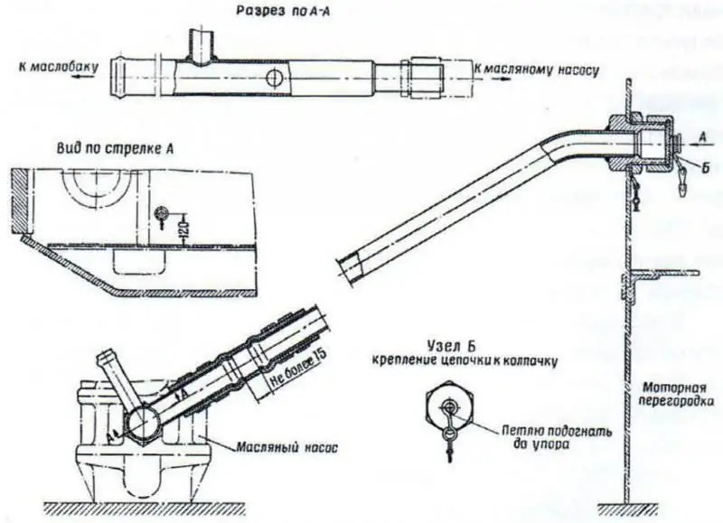
Constructive changes in the lubrication system of the IS-3 and IS-2 tanks to ensure trouble-free starting of engines at low ambient temperatures.
Before starting, the engine crankshaft was scrolled from the starter. If the value of the oil pressure at the engine inlet was 196-343 kPa (2-3, 5 kgf / cmg), this indicated the presence of liquid oil and normal operation of the oil pump. The standard oil pump (gear), as a rule, did not work at low temperatures due to oil thickening. Thus, the changes made to the lubrication system to ensure trouble-free engine start at low ambient temperatures have shown sufficient reliability and efficiency in operation.
In 1953, at the NIIBT proving ground on the IS-3 and IS-2 tanks, the installation of night vision devices of the TVN driver-mechanic designed by VEI im. Lenin. On some IS-2 tanks (depending on the design of the bow of the hull and the presence of the driver's "plug" inspection hatch), this device could be installed only without upper and lower prisms (later this device was called BVN. - Author's note). The absence of prisms reduced the loss of infrared rays and light in them, so the image in this device was brighter, all other things being equal, than in the TVN device. To illuminate the terrain, a FG-10 headlight with an infrared filter was used. Since 1956, the TVN (TVN-1) device has been included in the IS-3 tank kit.
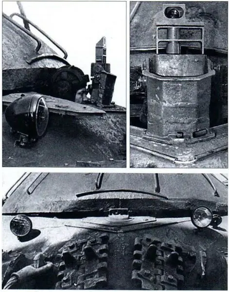
Installation of the night vision device of the driver-mechanic TVN-1 "in the marching way" (above) and "in the fighting way" in the IS-3 tank.
In 1954, at the NIIBT test site on one of the IS-3 tanks (No. 18104B), tests were carried out to check the gas content of the crew compartment and the effect of ventilation means and a device for ejection blowing of the barrel bore on the concentration of powder gases. So, in the period from May 28 to June 25, 1954, the machine was consistently tested by firing from the beginning with a standard D-25T cannon (13 shots were fired), and then by re-barrel - with a D-25TE cannon (64 shots were fired), equipped with an ejection the device for blowing the bore of the structure of the plant No. 172 (chief designer - M. Yu. Tsiryulnikov).
The test results showed that the accuracy of the battle from the D-25TE cannon both at the beginning and at the end of the tests was within the limits of the tabular norms. The installation of the ejector significantly influenced the moment of barrel imbalance, the value of which increased by almost 5.5 times (from 4.57 to 26.1 kgm).
When firing a cannon without using the standard ventilation means of the fighting compartment, the ejection device for blowing the barrel bore worked quite effectively: the average concentration of powder gases in the breathing zone of the loader decreased from 7.66 to 0.66 mg / l, or 48 times, in the zone respiration of the tank commander - from 2.21 to 0.26 mg / l, or 8.5 times.
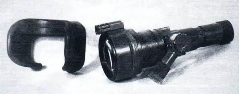
Night vision device of the driver-mechanic BVN for installation in the IS-2 sleeve.
The efficiency of the blowdown when firing with the engine running (at the crankshaft speed of 1800 min 1) and the fan, which created the greatest air depression in the fighting compartment of the vehicle, compared with the same firing from a cannon without ejection blowing, was practically absent.
The presence of an ejection device significantly reduced the number of backfire occurrences and required placing a load weighing 50-60 kg on a fixed fence. After some refinement and solution of the issues of balancing the gun, the ejection device for purging the barrel bore after the shot was recommended for mass production and installation on new guns of heavy T-10 tanks.

Tank IS-3 with the D-25TE cannon.
To determine the effect of the explosion of a new TMV anti-tank mine (TNT and ammatol equipment) designed by the NII-582 with various overlap of its tracks, as well as the mine resistance of various objects of armored vehicles at the NIIBT test site in the period from July 29 to October 22, 1954, was subjected to testing tank IS-210 *. Before the start of the tests, the vehicle was fully equipped, brought to combat weight and installed new tracks, which were assembled from tracks made from silt of KDLVT steel (with and without molybdenum (Mo) content), as well as from LG-13'89 steel.
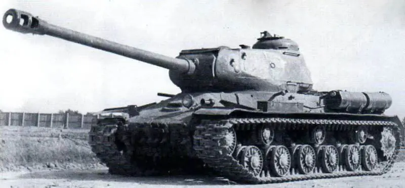
Tank IS-2 with installed sensors, prepared for tests for undermining the chassis. NIIBT test site, July 1954
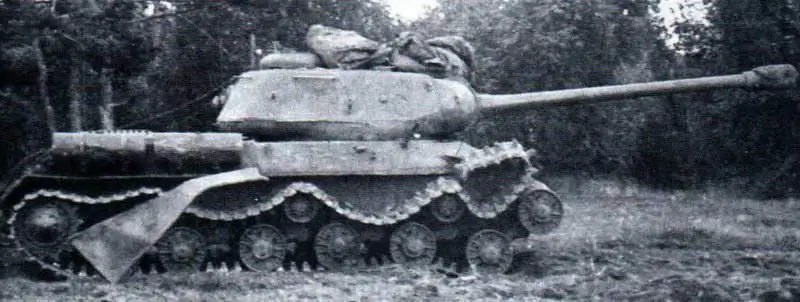
The nature of the damage to the IS-2 tank during a mine explosion (with overlapping 1/3 of the diameter) under the first left road roller. NIIBT polygon.
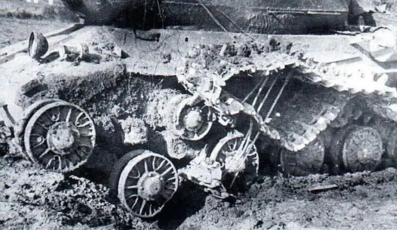
The nature of the destruction of the undercarriage of the IS-2 tank from the explosion of a mine of TNT equipment with an overlap of 1/2 of the diameter (tracks made of steel KDLVT (SMO).
In total, during tests under the tracks of the IS-2 tank, 21 TMV mines of TNT equipment with a mass of 5.5 kg were detonated both without penetration, and with penetration with various overlapping tracks. In some experiments, experimental animals (rabbits) were used to determine the effect of detonation on the crew.
As shown by the test results, when a mine exploded under a track made of KDLVT steel (without Mo) '91, with overlapping 1/3 of the mine's diameter, the caterpillar was completely interrupted. As a rule, from the track lying on the mine, and the tracks connected with it, pieces were beaten off approximately to the level of the road roller rim, further destruction proceeded along the lugs. After each detonation, only broken track links were required (an average of five).
At the support and support rollers, the tires were slightly deformed, the bolts of the armored cap and the armor plugs were cut off. Cracks sometimes appeared in the wheels of the road roller, but the bearings of the rollers and balancers were not damaged. At the body of the machine, fenders and fenders were torn by welding, glass and a headlight bulb were destroyed, while the sound signal remained intact.
The tracks of the caterpillar, made of steel KDLVT (with Mo), had a slightly higher mine resistance. So, when a mine was blown up with an overlap of 1/3 of its diameter under such tracks, there were cases when the caterpillar did not interrupt, despite the fact that pieces of 150-160 mm were torn off the tracks (to the level of the road roller rim). In these cases, the tank did not receive any damage after the explosion, which would lead to its stop.
When a TNT mine exploded with an overlap of 1/2 of its diameter, the tracks made of KDVLT steel (with Mo) were completely interrupted. The destruction of the tracks occurred both along the body and in the places where the lugs and shanks passed into the body of the track. Other damage to the tank was similar to damage caused by a mine blasting with an overlap of 1/3 of its diameter, with the only difference that an explosion with an overlap of 1/2 of the diameter knocked down the roller travel stop. The limiter was destroyed along the section located near the weld, as well as in the plane of the tie bolt hole. In addition, the support roller axle was pressed out of the balance beam (together with the roller).
In the case of detonation of a TNT equipment mine weighing 5.5 kg, installed deeply (8-10 cm below the surface of the soil) under tracks with tracks made of KDLVT steel (with Mo) when overlapping 1/3 of its diameter, a complete destruction of the caterpillar was also observed, and the tank received damage, as when a mine was blown up without deepening with the same overlap. When a mine exploded under the second road roller, the axle of the roller together with the roller came out of the hole of the balance bar, and the travel stops of the balance bars of the second and third road rollers were destroyed. Under the tracks of KDLVT steel, one detonation of a mine filled with TNT weighing 6.5 kg with an overlap of 1/3 of the diameter in soil with high humidity was carried out. From the explosion of the mine, the caterpillar was completely torn apart in two places: under the road roller and above it. Moreover, a piece of the caterpillar was thrown from the car by 3-4 m. The explosion destroyed the outer bearing of the road roller, tore off the bolts of the armored cap and the support roller, and the balance bar travel stop was also knocked down. Since the complete destruction of tracks with tracks made of KDLVT steel by TVM mines equipped with TNT weighing 5.5 kg and overlapping 1/3 of the diameter occurred in almost most cases, further tests for blasting mines of a larger mass for these tracks of the IS-2 tank were not performed (according to TU, it was sufficient for the mine to interrupt the caterpillar with an overlap of 1/3 of the diameter).


